

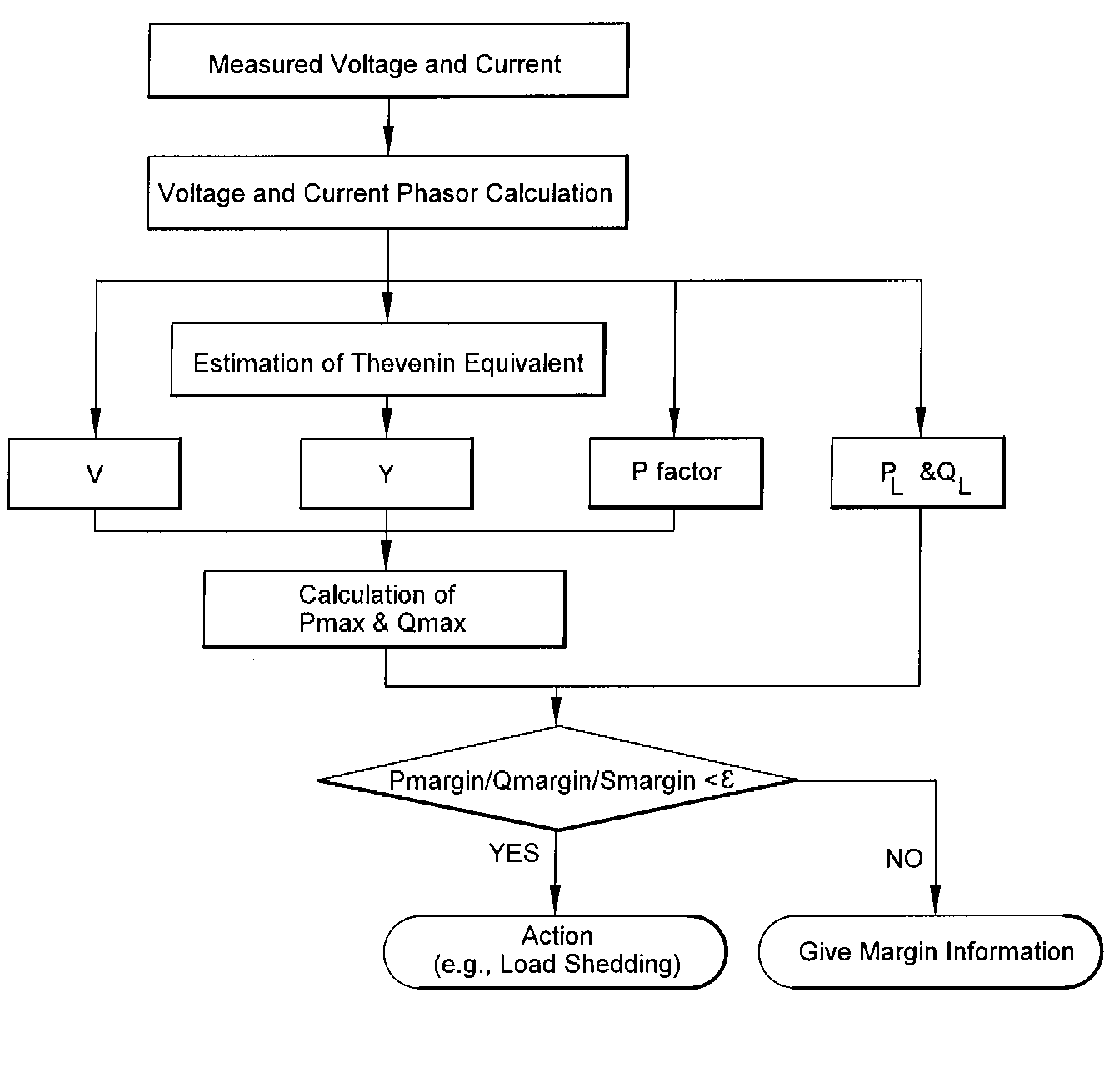
Method for voltage instability load shedding using local measurements
a voltage instability and load shedding technology, applied in the direction of electric variable regulation, process and machine control, instruments, etc., can solve the problems of high electricity supply and consumer costs, complex computation of actual system pv curves, and voltage magnitude alone is not a satisfactory indicator of the proximity to voltage instability. , to achieve the effect of improving the conventional uvls
- Summary
- Abstract
- Description
- Claims
- Application Information
AI Technical Summary
Benefits of technology
Problems solved by technology
Method used
Image

Examples
Embodiment Construction
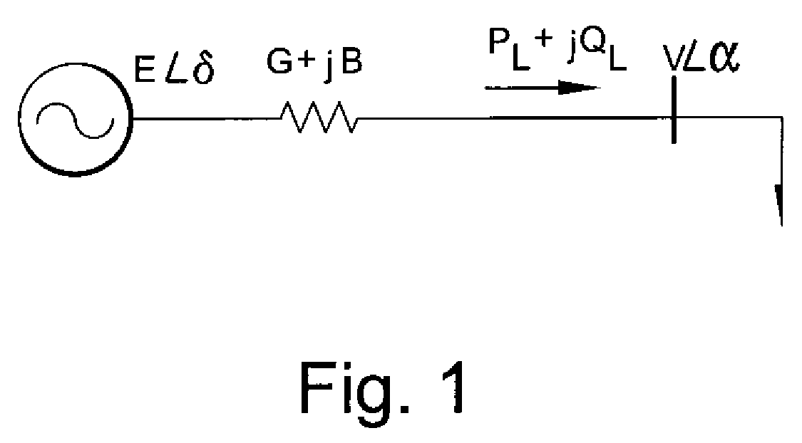
[0014]Referring now to FIG. 1, the real and reactive power transferred from the system to the load is
{PL=EVYcos(α-δ-β)-V2GQL=EVYsin(α-δ-β)+V2B(1)
Where Y is the magnitude and β is the angle of the Thevenin equivalent admittance G+jB
[0015]Dividing E2Y on both sides of Equation (1), it can be reformulated as:
{p=vcos(α-δ-β)-v2cosβq=vsin(α-δ-β)+v2sinβwherep=PLE2Y,q=QLE2Y,v=VE(2)
[0016]Moving v2 cos β and v2 sin β to the left sides and taking the square of the right and left sides and adding, the following equation is obtained:
(p+v2 cos β)2+(q−v2 sin β)2=v2 (3)
[0017]Substitute q with p·tan φ, where φ is the power factor of load.
From equation (3) is obtained:
p=−v2 cos φ cos(φ+β)+cos φ√{square root over (v2−v4 sin2(φ+β))} (4)
[0018]Taking the derivative and setting it equal to zero, the normalized critical voltage and maximum power is obtained:
∂p∂v=1-4v2+4v4sin2(φ+β)=0(5)vcritical2=1-cos(φ+β)2sin2(φ+β)=12[1+cos(φ+β)](6)pmax=cosφ2[1+cos(φ+β)](7)
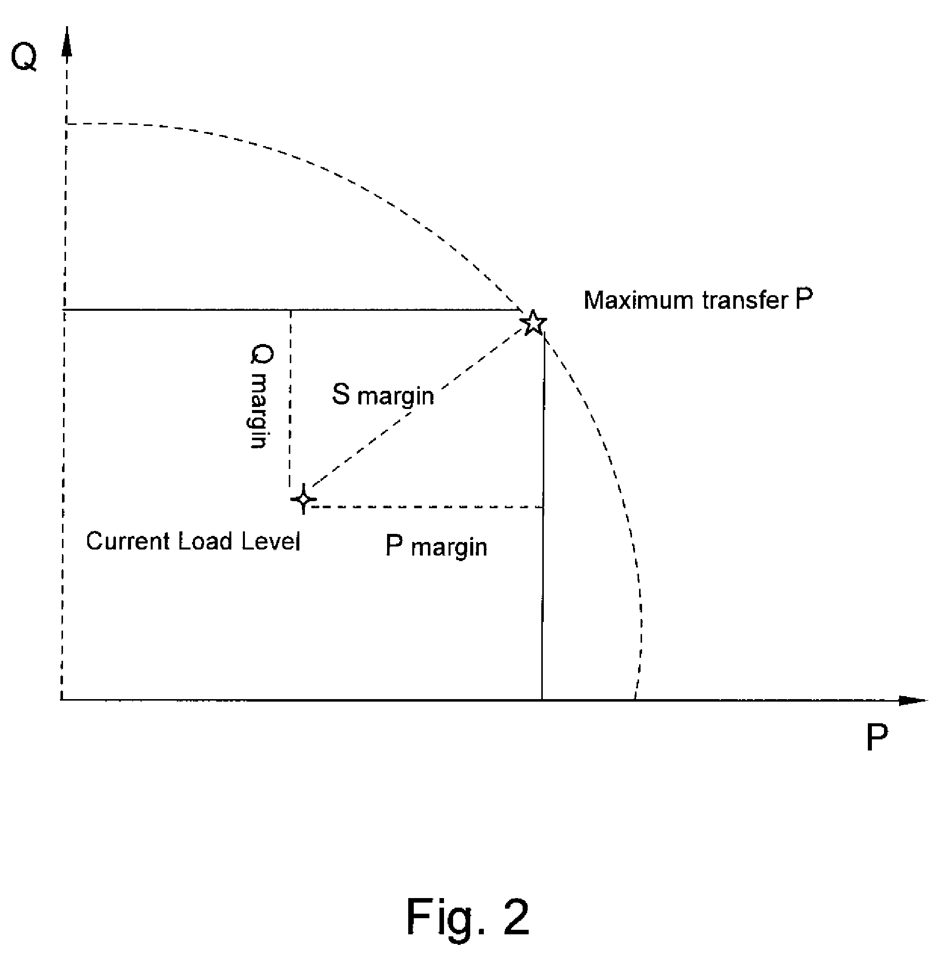
[0019]The maximum active and reactive transfer ...
PUM
 Abstract
Description
Claims
Application Information