Supercharge Your Innovation With Domain-Expert AI Agents!

Printhead Assembly Having A Fluid Transfer Member

a technology of fluid transfer member and printhead, which is applied in the direction of printing and inking apparatus, etc., can solve the problems of difficult manufacturing of such printheads, complicated assembly process, and inability to provide easy disassembly and assembly

Inactive Publication Date: 2008-04-17
MEMJET TECH LTD +1
View PDF6 Cites 1 Cited by
  • Summary
  • Abstract
  • Description
  • Claims
  • Application Information

AI Technical Summary

Benefits of technology

Facilitates the manufacture of printheads with variable dimensions, allows for easy replacement of defective tiles, and simplifies the assembly process by enabling the use of separable modules, improving manufacturing efficiency and maintenance.

Problems solved by technology

In this regard, due to the large variation in the required dimensions of such printheads, it is difficult to manufacture such printheads in a manner which caters for this variability.
Such an arrangement complicates the assembly process and does not provide for easy disassembly should the need to replace components other than just the defective tiles be necessary.

Method used


Image

  • Printhead Assembly Having A Fluid Transfer Member
  • Printhead Assembly Having A Fluid Transfer Member
  • Printhead Assembly Having A Fluid Transfer Member

Examples


Embodiment Construction

[0086] The exemplary embodiments of the present invention are described as a printhead assembly and a printhead module that is incorporated in the printhead assembly.

General Overview

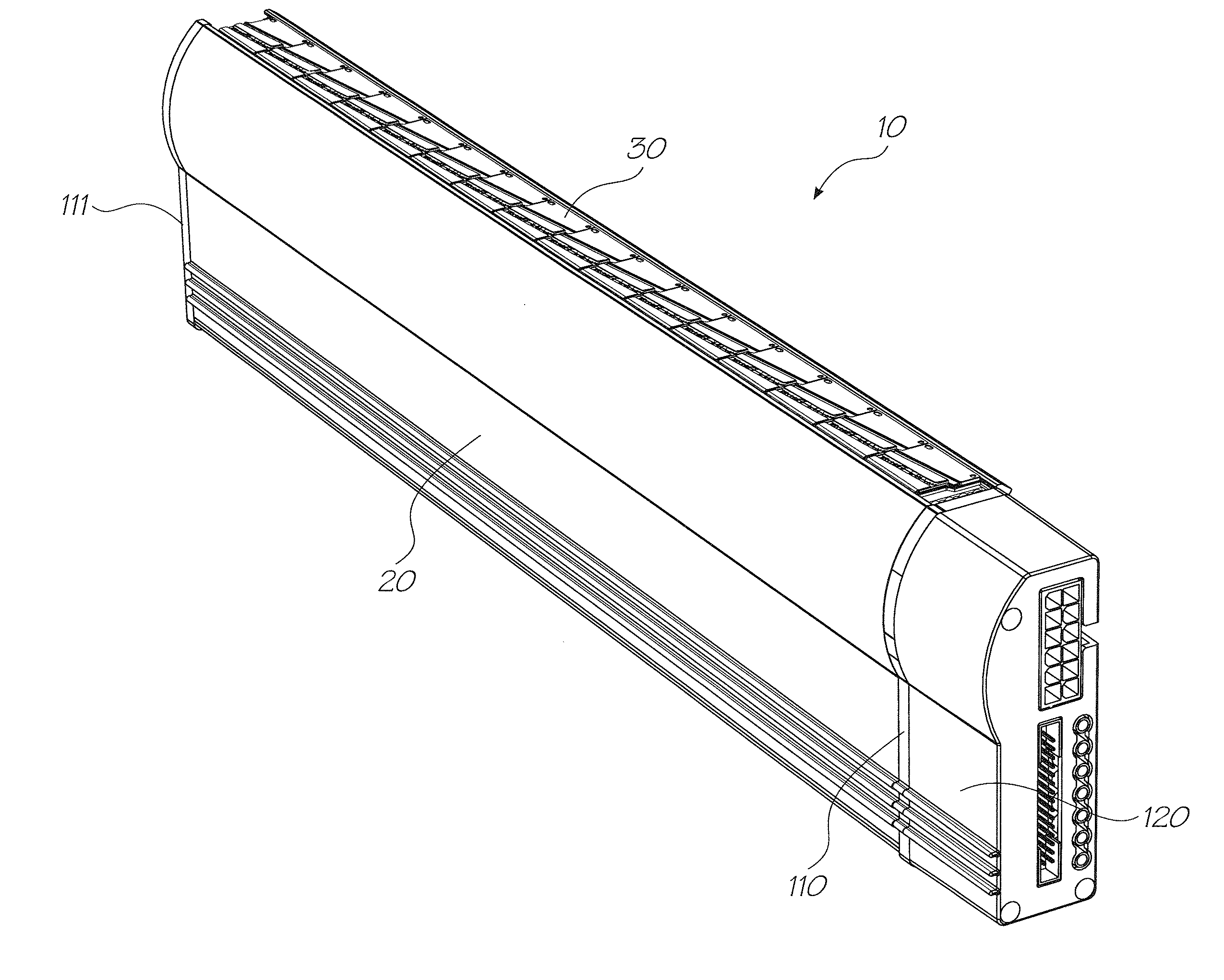
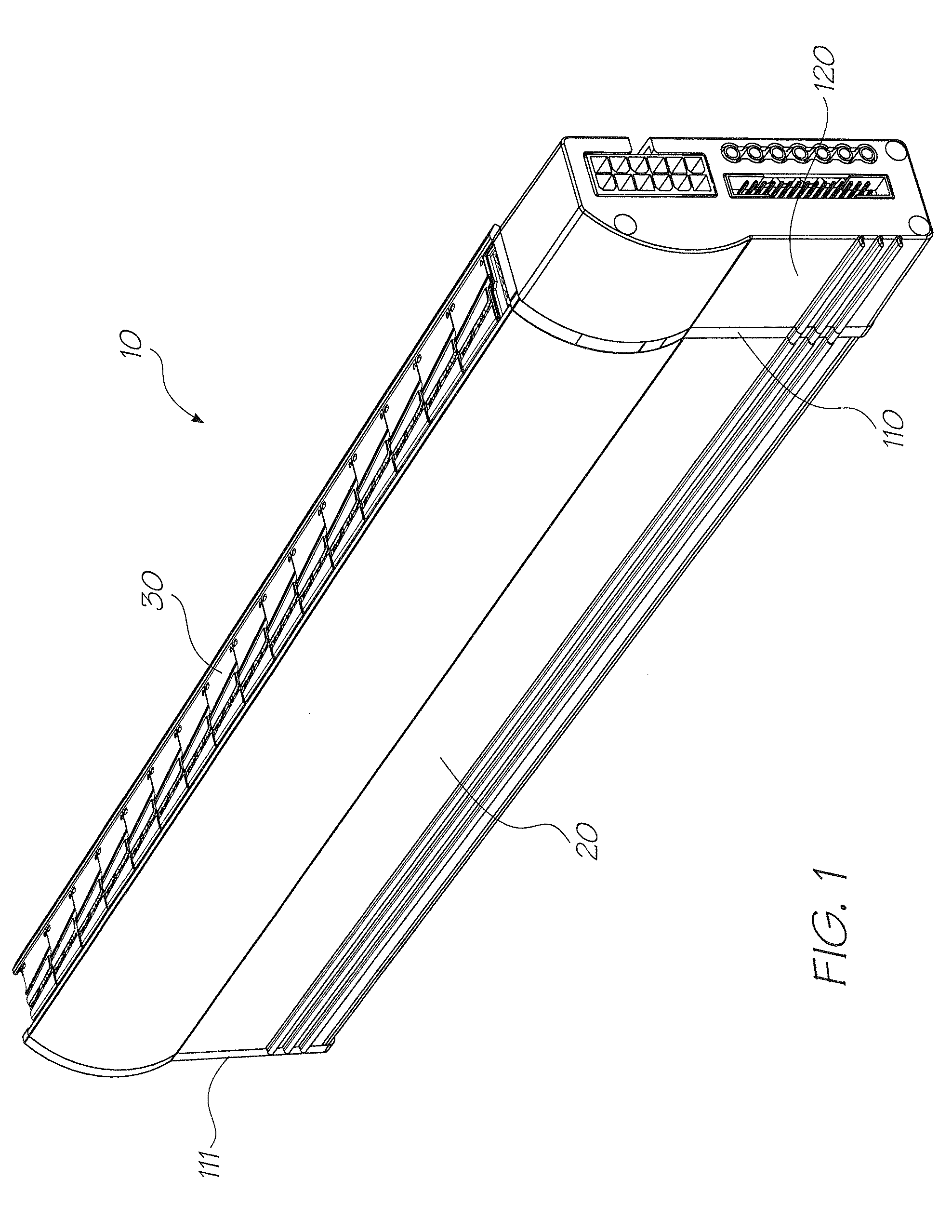
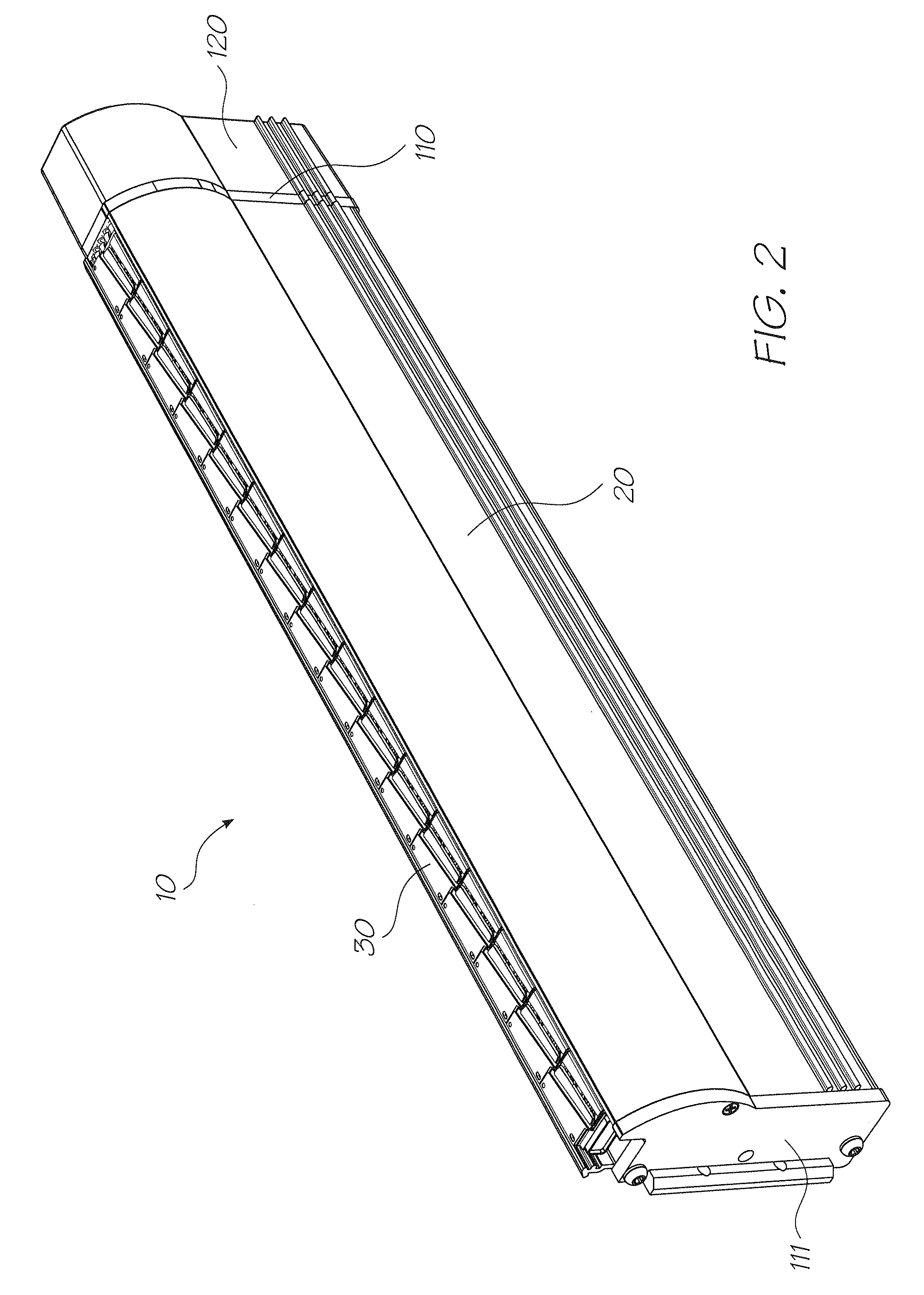
[0087] The printhead assembly 10 as shown in FIGS. 1 and 2 is intended for use as a pagewidth printhead in a printing system. That is, a printhead which extends across the width or along the length of a page of print media, e.g., paper, for printing. During printing, the printhead assembly ejects ink onto the print media as it progresses past, thereby forming printed information thereon, with the printhead assembly being maintained in a stationary position as the print media is progressed past. That is, the printhead assembly is not scanned across the page in the manner of a conventional printhead.

[0088] As can be seen from FIGS. 1 and 2, the printhead assembly 10 includes a casing 20 and a printhead module 30. The casing 20 houses the dedicated (or drive) electronics for the printhead assembly toget...


PUM


Abstract

A printhead assembly comprising: at least one printhead module comprising: at least two printhead integrated circuits, each of which has nozzles formed therein; a longitudinal extending fluid transfer member configured to support the at least two printhead integrated circuits, wherein the fluid transfer member includes a plurality of chambers which are in fluid communication with a supply of printing fluid and respective ports of the at least one printhead module; and an electrical connector for receiving electrical signals for the at least two printhead integrated circuits; a drive electronics part incorporating at least one controller which is connected to at least one of the at least two printhead integrated circuits via the electrical connector for controlling the printing operation of at least one of the at least two printhead integrated circuits; and a casing part for supporting the drive electronics part and the at least one printhead module.

Description

CROSS REFERENCE TO RELATED APPLICATION [0001] The present application is a continuation of U.S. application Ser. No. 10 / 760,238 filed on Jan. 21, 2004 all of which are herein incorporated by reference.FIELD OF THE INVENTION [0002] The present invention relates to a printhead unit for use in a printing system. More particularly, the present invention relates to a printhead assembly which is mountable to and demountable from a printing unit. CROSS-REFERENCE TO CO-PENDING APPLICATIONS [0003] The following applications have been filed by the Applicant simultaneously with the present application: 7156508715997270832717165834708089472014697090336715648910 / 76023310 / 760246708325772584227255423721998010 / 76025310 / 76025510 / 760209711819210 / 76019470775057198354707750410 / 760189719835510 / 76023210 / 76023171529597213906717890172229387108353710462910 / 76025410 / 76021010 / 760202720146810 / 76019810 / 760249723480210 / 7601967287846715651110 / 7602647258432709729110 / 76022210 / 760248708327310 / 76019210 / 76020310 / 7602...

Claims


Application Information

Patent Timeline
Patent Type & Authority Applications(United States)
IPC IPC(8): B41J2/14B41J2/145
CPCB41J2/145B41J2002/14435B41J2202/20B41J2202/19B41J2002/14491
Inventor SILVERBROOK, KIABERRY, NORMAN MICHEALJACKSON, GARRY RAYMONDNAKAZAWA, AKIRA
Owner MEMJET TECH LTD
Features
  • R&D
  • Intellectual Property
  • Life Sciences
  • Materials
  • Tech Scout
  • Unparalleled Data Quality
  • Higher Quality Content
  • 60% Fewer Hallucinations
Learn More