Plant Watering and Shading Device

a shading device and plant technology, applied in the field of plant husbandry, can solve the problems of not providing means for rainwater collection, no additional shading provided by the watering device, and no cover device adjustabl

Inactive Publication Date: 2008-04-24
JOHNSON JULIE S
View PDF17 Cites 71 Cited by
  • Summary
  • Abstract
  • Description
  • Claims
  • Application Information

AI Technical Summary

Benefits of technology

[0010]The shaft preferably includes a valve mechanism therein proximate the bottom end. The valve mechanism, when in a closed position, prevents water in the shaft from reaching the bottom end of the shaft. In an open position, the valve mechanism allows water to flow from the shaft into the bottom end of the shaft, and then out through the spike. In one embodiment of the invention, the valve mechanism is a ball valve having a buoyant ball captured within the bottom end of the shaft. A seal within the shaft is adapted to receive the ball against a lower side thereof to close the valve.

Problems solved by technology

However, as such shade devices often block rainwater from reaching the plant, separate watering means must be provided with such devices.
However, none of the watering devices additionally provides for shading.
Further, such a covering device is not adjustable for varying the degree of covered protection the plant receives.
The—362 device does not provide means to collect rainwater, and instead includes sprinkler means for delivery pressurized water to plants from a municipal source, for example.
The—646 device, on the other hand, makes no provision for adjusting the amount of shade that plants receive.
The—646 device, further, is quite bulky and not well-suited to standard house plants in plant pots, for example.

Method used


Image

  • Plant Watering and Shading Device
  • Plant Watering and Shading Device
  • Plant Watering and Shading Device

Examples


Embodiment Construction

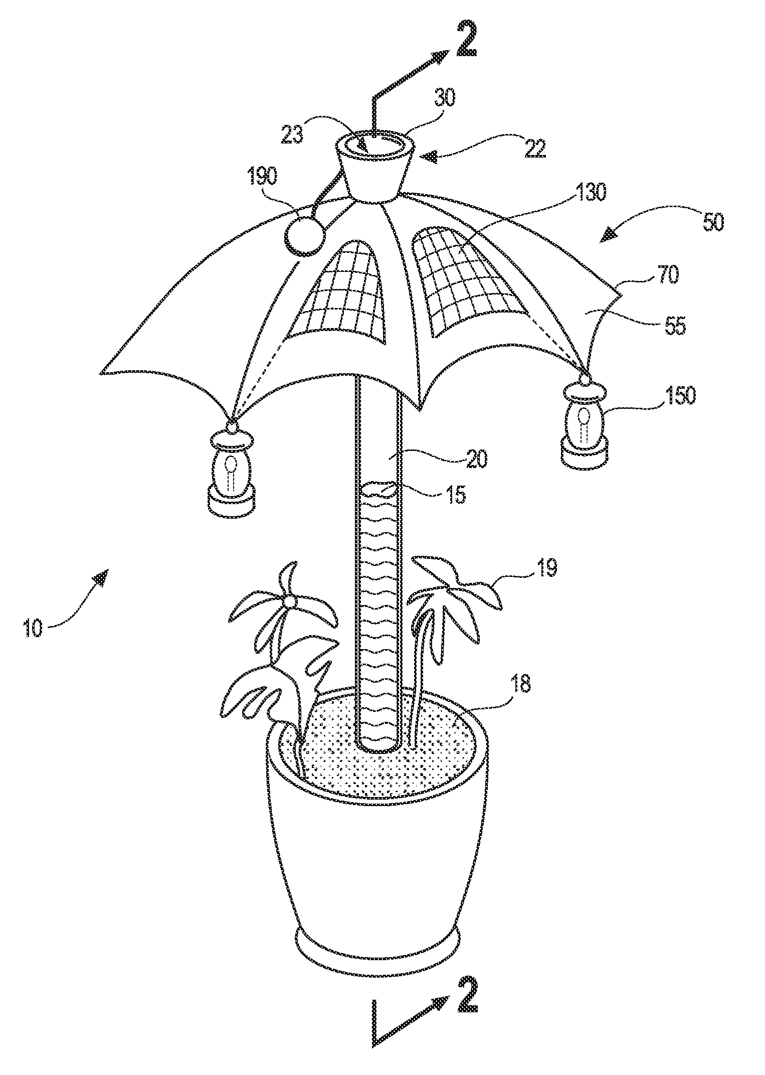
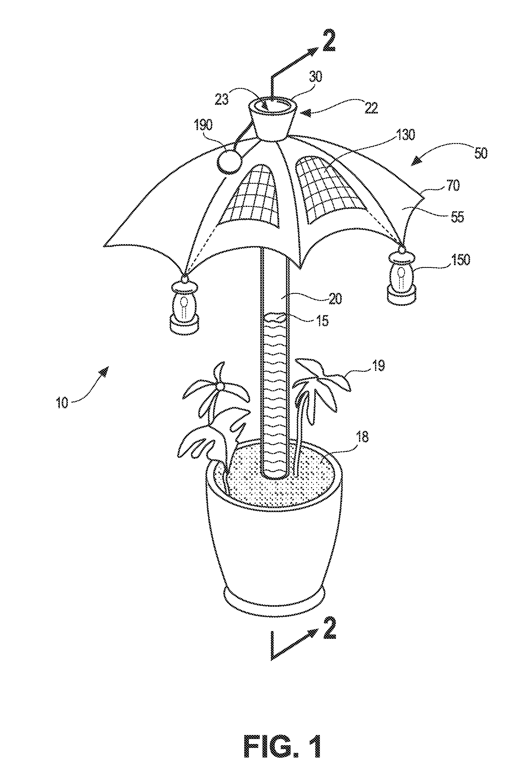
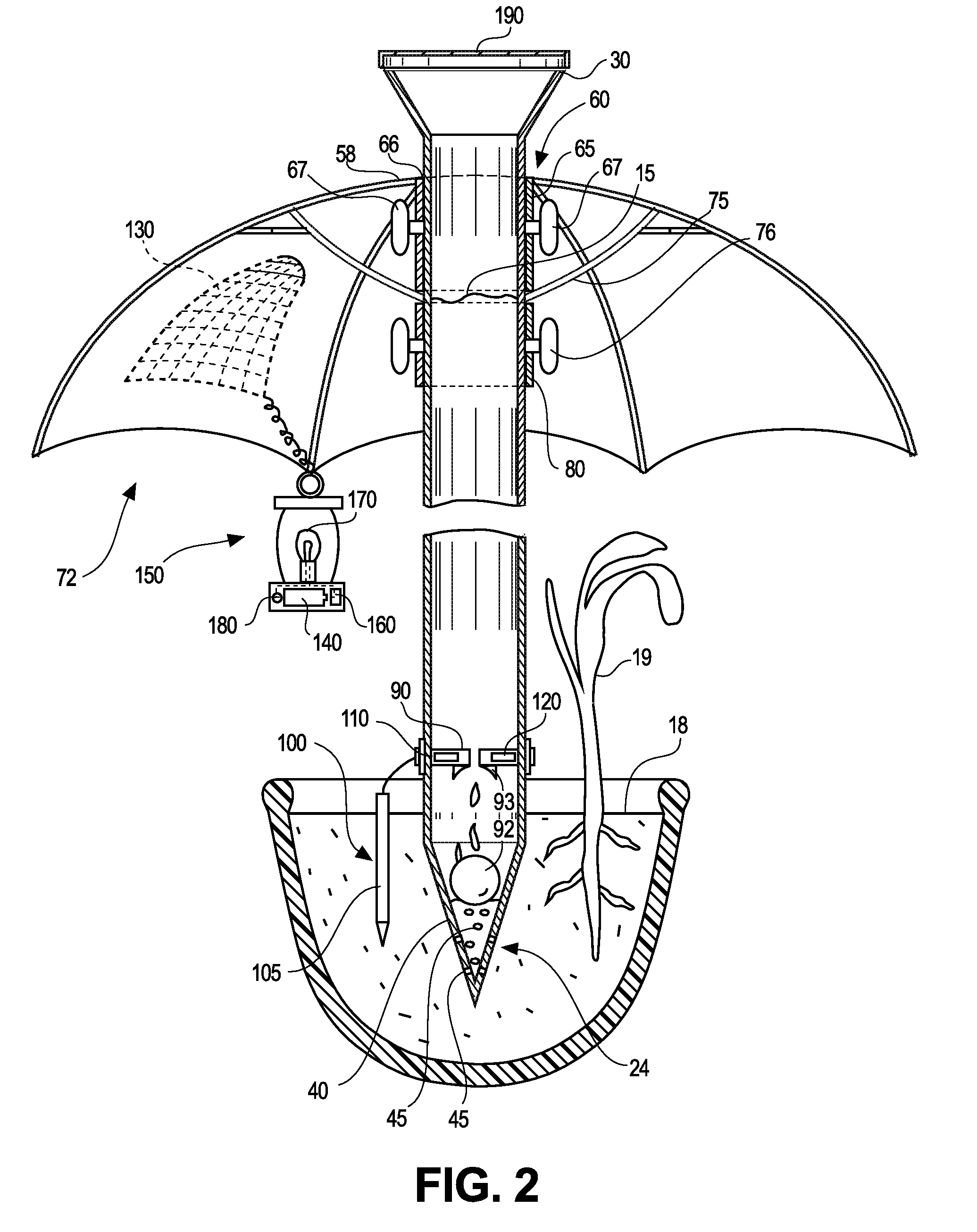
[0019]FIG. 1 illustrates a watering and shading device 10 for at least one plant 19. The device 10 comprises an elongated substantially hollow shaft 20 having a top end 22 and a bottom end 24. The top end 22 terminates in a preferably flared funnel-shaped opening 23 for receiving water 15, and the bottom end terminates in a soil-penetrating spike 40 for inserting into soil 18. The spike 40 includes at least one aperture 45 therein for allowing water 15 to pass from the inside of the hollow shaft 20 therethrough. The shaft 20 is preferably made from an extruded plastic tube, injection molded plastic, or the like. A non-porous cover 190 may be further included for attaching to the opening 23 at the top end 22 of the shaft 20 for preventing water 15 from filling the shaft 20. The shaft 20 is preferably transparent or translucent so that the amount of water 15 within the shaft 20 may be readily visible.

[0020]In one embodiment of the invention, the shaft 20 is telescoping and as such hei...


PUM


Abstract

A watering and shading device for at least one plant is disclosed. The device comprises an elongated substantially hollow shaft. A top end of the shaft terminates in a preferably flared funnel-shaped opening for receiving water, and a bottom end terminates in a soil-penetrating spike for inserting into soil. The spike includes at least one aperture therein for allowing water to pass from the inside of the hollow shaft therethrough. The device also includes a shading umbrella that comprises at least one non-transparent panel attached at one portion thereof to a shaft attachment means. The umbrella may be selectively placed in a deployed position or a collapsed position at a selected height along the shaft. The shaft includes a valve mechanism therein proximate the bottom end controlled by a moisture detection means for regulating the position of the valve mechanism based upon the soil moisture level. At least one solar-powered lantern may be included, fixed to the shading structure, and activated upon a photovoltaic cell detecting darkening conditions.

Description

CROSS-REFERENCE TO RELATED APPLICATIONS[0001]Not Applicable.STATEMENT REGARDING FEDERALLY SPONSORED RESEARCH AND DEVELOPMENT[0002]Not Applicable.FIELD OF THE INVENTION[0003]This invention relates to plant husbandry, and more particularly to a combination plant shade and water reservoir apparatus.DISCUSSION OF THE RELATED ART[0004]In the field of plant husbandry, often it is desirable to provide certain types of plants shade from direct sunlight in order to promote optimal growth. Plant shades are typically large tent-like structures, but umbrella-like structures have also been used (such as in U.S. Pat. No. 3,706,160 to Deibert on Dec. 19, 1972; U.S. Design Pat. D513,117 to Raede on Dec. 27, 2005; and indirectly in U.S. Pat. No. 6,862,843 to Missry on Mar. 8, 2005. Such patents, and particularly the—160 patent, can provide not only shade to plants but also can often provide frost protection. However, as such shade devices often block rainwater from reaching the plant, separate water...

Claims


Application Information

Patent Timeline
Patent Type & Authority Applications(United States)
IPC IPC(8): A01G29/00A01G9/02
CPCA01G13/0212A01G29/00A01G27/006Y02P60/12
Inventor JOHNSON, JULIE S.
Owner JOHNSON JULIE S
Why Eureka
Try Eureka