Rotating shaft of shutter louver

a shutter louver and rotating shaft technology, applied in the direction of building components, constructions, building structures, etc., can solve the problems of affecting the use of the rotating shaft, the general difficulty of the rotating shaft being detached, and the continuous expansion of the frame mounting hole, so as to achieve the effect of easy and secure detachmen

Inactive Publication Date: 2008-04-24
NIEN MADE ENTERPRISE CO LTD
View PDF11 Cites 7 Cited by
  • Summary
  • Abstract
  • Description
  • Claims
  • Application Information

AI Technical Summary

Benefits of technology

[0011]In view of the above, the main technology problem to be solved by the present invention is to provide a rotating shaft of a shutter louver, wherein a gripping portion used for bearing against the frame mounting hole is disposed on the shaft bushing, so as

Problems solved by technology

However, the rotating shaft always cannot be used to avoid getting loose caused by the rotation of the louver, thus, some necessary designs are made on the shaft to prevent the loosening circumstance from occurring again, and most of the common rotating shafts are just like the one disclosed in U.S. Patent Publication NO.
(1) The shaft bushing wing is easily damaged. Generally, the shaft bushing wing is sheet-shaped or strip-shaped, and its cross-sectional view is bar-shaped and quite small in width. When the aperture of the frame mounting hole is excessively close to the outside diameter of the cylindrical shaft bushing that the cylindrical shaft bushing cannot be inserted into the frame mounting hole, the cylindrical shaft bushing is forced into the frame mounting hole by pressing, thus the shaft bushing wing is damaged, deformed, or cracked in shape due to the excessive large pressure or the counterforce from the inner side of the frame mounting hole that cannot be born any more, so that the cylindrical shaft bushing cannot be fixed in the frame mounting hole. Moreover, as the rotation of the louvers, the damaged and deformed shaft bushing wing continuously rub with the inner side of the frame mounting hole, thus, the aperture of the frame mounting hole is continuously enlarged.
(2) The aperture of the frame mounting hole is changed due to the variation of the climate, so that the cylindrica

Method used


Image

  • Rotating shaft of shutter louver
  • Rotating shaft of shutter louver
  • Rotating shaft of shutter louver

Examples


Embodiment Construction

[0031]To further understand the object, structure, feature, and function of the present invention, the present invention is further described below in detail with reference to embodiments and accompanying drawings.

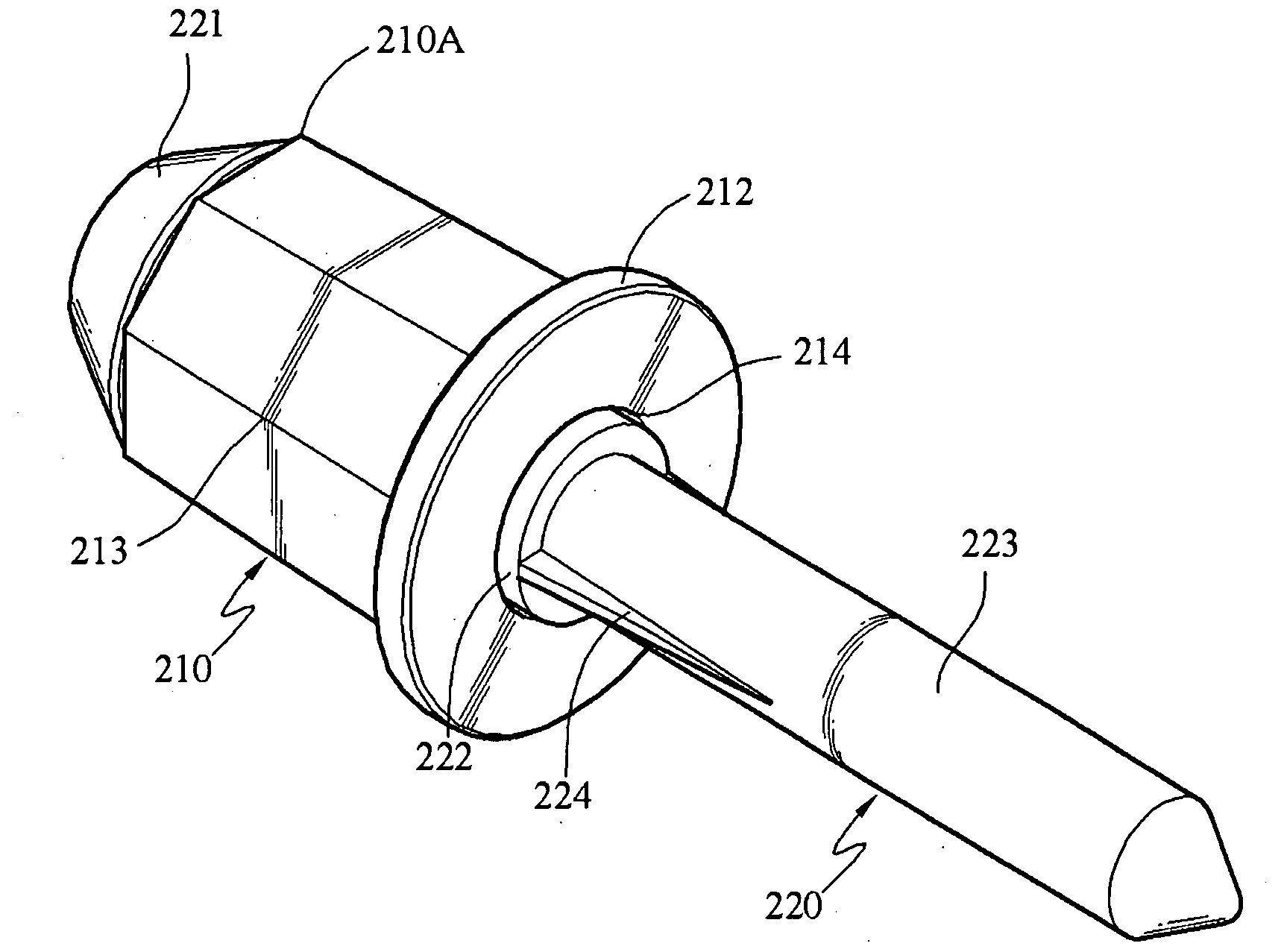
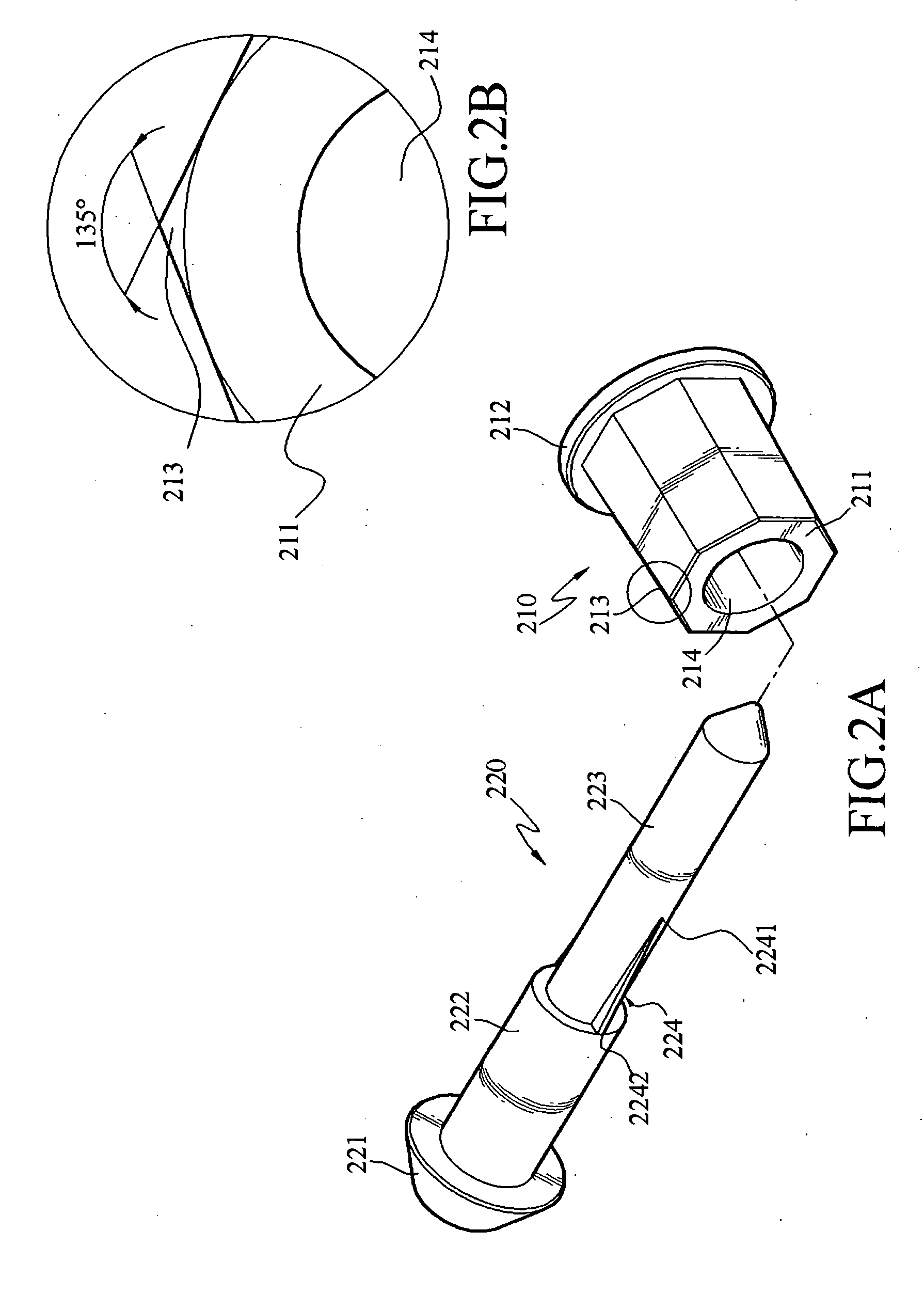
[0032]Referring to FIGS. 2A and 2B, they are a structure diagram of components and a cross-sectional view of a shaft bushing according to a first preferred embodiment of the present invention. A shaft bushing 210 and a shaft 220 are included. The shaft bushing 210 has a body 211, a flange 212, and a plurality of gripping portions 213. A shaft hole 214 is formed to pass through front and back ends of the body 211, the flange 212 is disposed on the back end of the body 211, and the gripping portions 213 are protruded from the outer edge of the body 211, and symmetrically about the shaft center of the body 211. The upper sides of the ramps of the gripping portions 213 are connected to form a top edge, the down sides are spaced apart for a predetermined distance and connected ...


PUM


Abstract

A rotating shaft of a shutter louver is provided, which is inserted into a louver mounting hole and frame mounting hole, so as to connect the louver to the frame. The rotating shaft is formed by a shaft bushing and shaft, wherein a shaft hole is formed through the body of the shaft bushing, a flange is disposed on the body and a gripping portion is protruded from the body. The shaft is accommodated within the shaft hole, and a fin is protruded from the shaft tail. When the rotating shaft is inserted into the frame mounting hole, the gripping portion is used to bear against the inner side of the frame mounting hole and thereby applying a force to grip the rotating shaft, and cooperating with the operation of gripping the louver mounting hole by the fin, the louver is positioned on the frame quickly and firmly.

Description

BACKGROUND OF THE INVENTION[0001]1. Field of Invention[0002]The present invention relates to a rotating shaft of a shutter louver, and more particularly, to a rotating shaft of a shutter louver, which utilizes a gripping portion protruded from the outer edge of the shaft bushing to cooperate with a fin disposed on the shaft tail to pivotally connect the louver and position the louver on the frame.[0003]2. Related Art[0004]Current shutter or louvered windows always have a plurality of louvers thereon for adjusting the airflow and the light. Generally, a rotating shaft is disposed between the louvers and the frame of the shutter, so as to position the louvers on the frame. However, the rotating shaft always cannot be used to avoid getting loose caused by the rotation of the louver, thus, some necessary designs are made on the shaft to prevent the loosening circumstance from occurring again, and most of the common rotating shafts are just like the one disclosed in U.S. Patent Publicati...

Claims


Application Information

Patent Timeline
IPC IPC(8): E06B7/084
CPCE06B7/084
Inventor YANG, FU-YUNG
Owner NIEN MADE ENTERPRISE CO LTD
Why Eureka
Try Eureka