Device and method for driving LED

a technology of led lighting and diodes, which is applied in the direction of electrical equipment, electrical variable regulation, instruments, etc., can solve the problems of large power consumption at current-limiting resistors, and large device size and weight, and achieves simple constitution, high power efficiency, and small size

Active Publication Date: 2008-04-24
AVAGO TECH INT SALES PTE LTD
View PDF2 Cites 180 Cited by
  • Summary
  • Abstract
  • Description
  • Claims
  • Application Information

AI Technical Summary

Benefits of technology

The technical effect of this patent is that it provides an LED lighting device with high power efficiency and does not require special measures against noise. Additionally, the device has a small size and low cost due to its simplified construction compared to traditional devices.

Problems solved by technology

The technical problem addressed in this patent is how to create an LED lighting device that solves issues related to size, cost, and power efficiency while also addressing noise concerns associated with DC/DC converters. Additionally, if a lighting system uses white LEDs instead of traditional options such as electrical bulbs or fluorescent lamps, these challenges become even more significant.

Method used


Image

  • Device and method for driving LED
  • Device and method for driving LED
  • Device and method for driving LED

Examples


first embodiment

1. FIRST EMBODIMENT

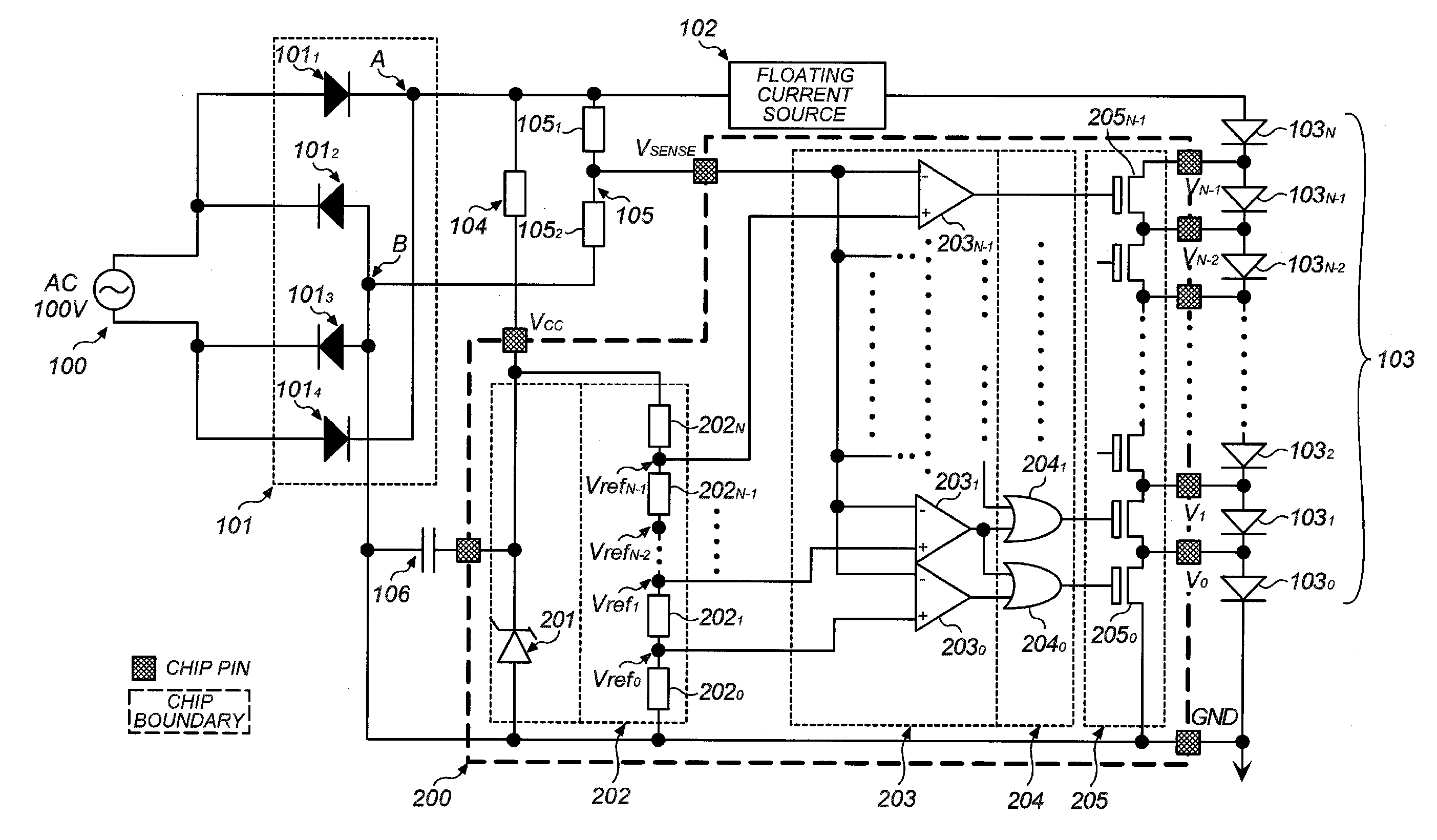
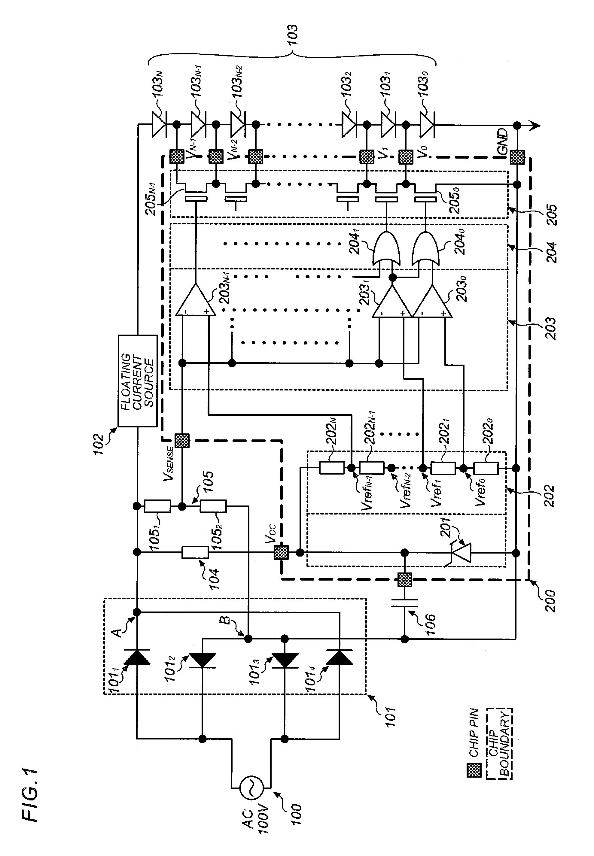
[0040] Hereafter, a first embodiment of the present invention is described by referring to FIG. 1. FIG. 1 is a schematic block diagram of an LED lighting device according to the first embodiment of the present invention.

[0041] An AC source 100 and a rectifier circuit 101 in FIG. 1 may be similar to those of conventional constitutions shown in FIGS. 8 to 10. As the AC source for an LED lighting device, a commercial source (having, for example, 100V to 220V and 50 Hz to 60 Hz) is generally used in consideration general versatility, but an AC source other than a commercial source may be used. Use of a single-phase AC source is assumed in this embodiment, but three-phase AC, etc. may be used as the source.

[0042] Numeral 101 denotes a full-wave rectifier circuit comprised of four rectified diodes 1011, 1012, 1013, and 1014, which rectifies a commercial AC source to output a rectified voltage waveform, as exemplified in FIG. 4, between a plus output terminal A and a m...

second embodiment

2. SECOND EMBODIMENT

[0068] Next, a second embodiment of the present invention is described by referring to FIG. 7. This embodiment has a constitution equivalent to one shown in FIG. 1 except that LEDs are arranged in parallel and a lighting LED selection circuit 204 and a switch circuit 205 are modified to a control logic circuit 204′ and a switch circuit 205′. Thus, the remaining parts of this embodiment are the same as those shown in FIG. 1.

[0069] In FIG. 7, LEDs 103′0-1 to 103′(N-1)-3 are divided into N number of blocks each having three LEDs as indicated by dotted frames. These blocks include block 0 comprised of 103′0-1, 103′0-2, and 103′0-3; block 1 comprised of 103′1-1, 103′1-2, and 103′1-3; likewise, block 2, block 3, . . . , block (N−2); and finally block (N−1) comprised of 103′(N-1)-1, 103′(N-1)-2, and 103′(N-1)-3. N represents an integer of not less than 1, which can be properly set depending on embodiment requirement.

[0070] In this embodiment, LEDs of each block are co...


PUM


Abstract

An LED lighting device of AC power-driven type having a comparatively simple constitution and a high power efficiency. The device compares a signal voltage (rectified voltage) obtained by rectifying an AC source with a predetermined reference voltage and controls ON/OFF of a driving current to each LED of an LED array in response to a comparison result. In this constitution, a large voltage of AC source enables lighting of more number of LEDs, while a small voltage thereof enables lighting of less number of LEDs, thus enhancing power efficiency of the LED lighting device.

Description


Claims


Application Information

Patent Timeline
Owner AVAGO TECH INT SALES PTE LTD
Why Eureka
Try Eureka