

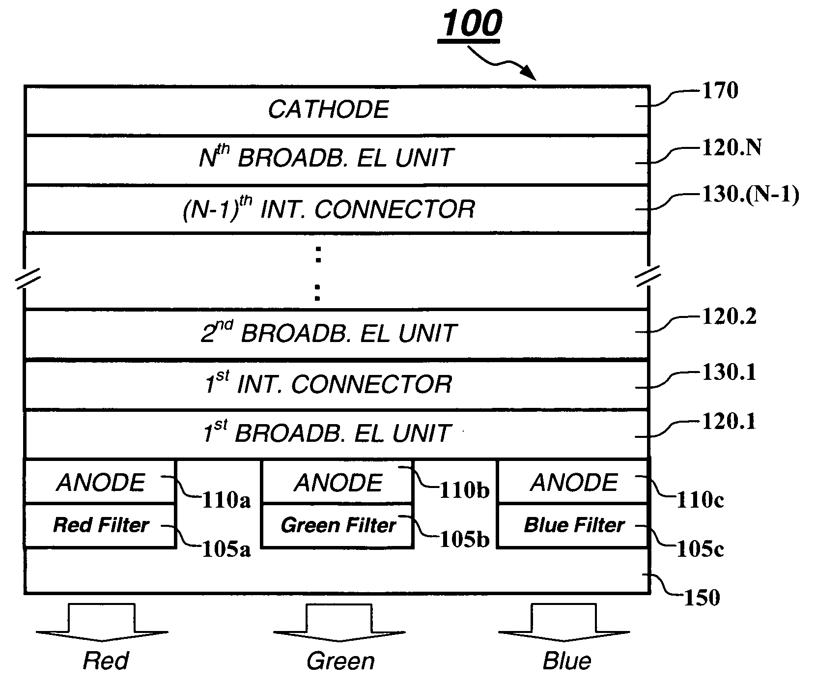
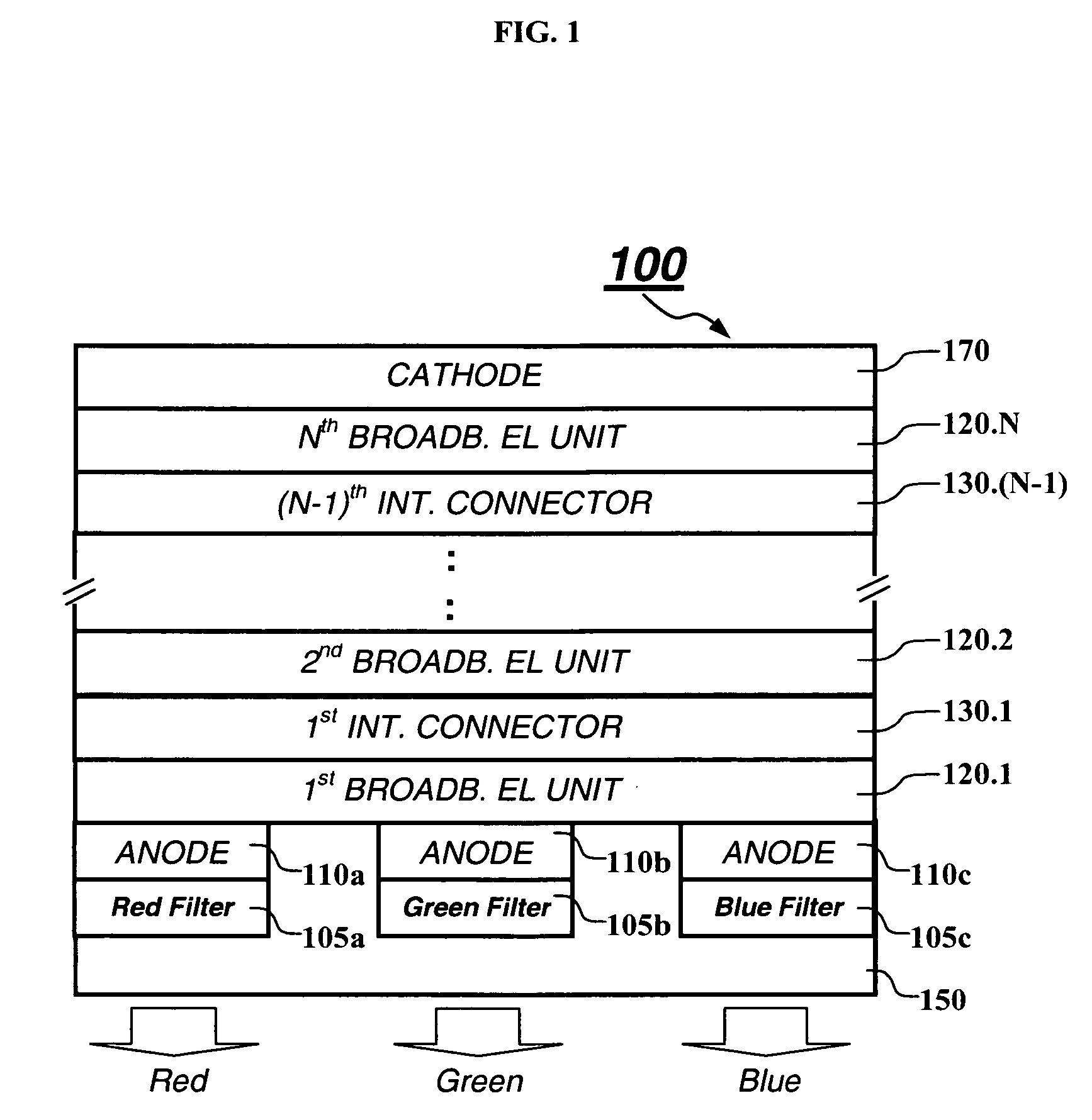
White light tandem OLED display with filters
a technology of oled display and white light, which is applied in the direction of discharge tube luminescnet display, discharge tube/lamp details, electric discharge lamps, etc., can solve the problems of difficult to achieve light emission with strong intensity, difficult to balance the recombination of holes and electrons in these three layers to provide balanced emission, and achieve effective oled display. , the effect of improving color gamut and power efficiency
- Summary
- Abstract
- Description
- Claims
- Application Information
AI Technical Summary
Benefits of technology
Problems solved by technology
Method used
Image

Examples
examples
[0179] The present invention and its advantages are better appreciated by the following inventive and comparative examples. In the following, mixed compositions are described in terms of percentages by volume, as are commonly used in the art. After deposition of the OLED layers each device was then transferred to a dry box for encapsulation. The OLED has an emission area of 10 mm2. The devices were tested by applying a current of 20 mA / cm2 across electrodes. The performance of the devices is given in Table 1. Using the color filter spectra of FIG. 4 and the emission spectrum of each example, the color and efficiency of the filtered red, green and blue colors were calculated and provided in Table 2.
[0180] Composite Efficiency near D65 white point was obtained by taking the luminance efficiency and the color of the R, G, B components through the color filters. The individual color luminance contribution and the respective current density were calculated to obtain a certain luminance ...
examples 1-6 (comparative)
Single Broadband EL Units
[0181] It is useful to begin with comparative OLEDs having only a single broadband EL unit. This makes the performance of tandem OLEDs having multiple EL units easier to understand.
examples 7-10
illustrate tandem OLED devices
Example 7 (Comparative)
[0228] Over a clean glass substrate, an 85 nm thick indium tin oxide (ITO) was provided. The ITO surface was treated with a plasma oxygen etch, followed by plasma deposition of a 0.5 nm layer of a fluorocarbon polymer (CFx) as described in U.S. Pat. No. 6,208,075. The following layers were deposited over CFx layer in the following sequence by evaporation from heated boats under a vacuum of approximately 10−6 Torr:
First Broadband EL Unit
[0229] a) a 10 nm HIL of Formula M1;
[0230] b) a 60 nm HTL of NPB;
[0231] c) a 20 nm yellow light-emitting layer including 77% NPB (as host) with 3% yellow-orange emitting dopant as shown in Formula C7 and 20% anthracene derivative of formula AH3 as a stabilizer;
[0232] d) a 47 nm blue emitting layer including 92.5% AH3 host with 1.5% TBP (Formula H2) as blue emitting dopant and 6% NPB;
Intermediate Connector
[0233] e) 25 nm thick n-type doped organic layer, including 49 volume % Bphen and 49 v...
PUM
 Abstract
Description
Claims
Application Information