
LED light bulb having an LED light engine with illuminated curved surfaces

a technology of led light bulbs and led light engines, which is applied in the field of light emitting diodes (led) light bulbs, can solve the problems of inconvenient manufacturing process, inconvenient design of led light bulbs, and inability to meet the needs of lighting and heating equipment,

Inactive Publication Date: 2012-07-24
SU ALLEN HUI LONG
View PDF15 Cites 64 Cited by
  • Summary
  • Abstract
  • Description
  • Claims
  • Application Information

AI Technical Summary

Benefits of technology

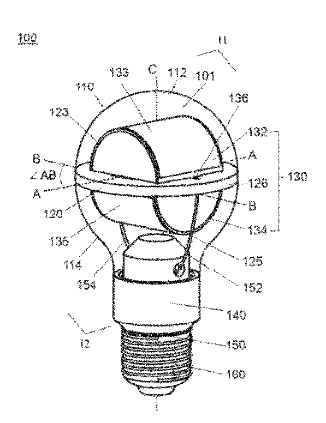
[0008]The present invention provides a novel lighting apparatus. According to one aspect of the present invention, an LED light bulb capable of providing an improved illumination having direct lights shone or projected to at least six different sides of the light bulb is provided. Such that a substantially spherical illumination with dispersed lights in multiple directions and different illumination zones may be advantageously obtained from the LED light bulb and preferably without excess uses of reflective means or modification to existing fixtures.
[0009]Another aspect of the present invention is to provide an LED light engine utilizing a minimal number and / or variation of individual LED module to minimize the inconsistency among different LED modules involved therein while providing an improved illumination. The manufacturing and preparation processes associated with the LED light engine may too be facilitated and may result in a greater consistency.
[0010]A further aspect of the present invention is to provide an LED light bulb having an effective cooling structure utilizing an increased surface area of curved illumination surfaces of an LED light engine as well as the space and structure configured therein. It is too preferably that an enhanced cooling structure or system may be provided to effectively cool the LED light engine without disturbing an improved illumination provided thereby for the LED light bulb as a whole.
[0011]A still further aspect of the present invention is to provide an LED light bulb having a mechanical structure involving less moving parts to prevent or reduce the likelihood of component failures as well as to facilitate manufacturing assembly, component preparation and parts recycling while providing an improved illumination with effective cooling.
[0013]According to another embodiment of the present invention, an LED light bulb utilizing high power LED modules with illuminated curved surfaces as an LED light engine with an enhanced cooling structure is provided. The light transmissive shell of the LED light bulb may preferably include first and second envelopes attached to a thermally conductive support block onto which the LED light engine having an increased illuminated surface area may be attached. Likewise, the LED light engine may further comprise first and second LED modules with illuminated curved surfaces curved about first and second center axes respectively to provide an improved illumination in multiple directions. The first center axis of the first illuminated curved surface of the first LED module may preferably be substantially perpendicular to the second center axis of the second illuminated curved surface of the second LED module such that direct lights may be shone or projected to at least six different sides of first and second illumination zones of the light bulb. In an explanatory example, said first illumination zone may include at least the top and two lateral sides, such as left and right, of the light bulb and said second illumination zone may include at least the bottom and the other two lateral sides, such as front and rear, of the light bulb. Furthermore, additional air channels may be provided to enhance the heat dissipation of the high power LED light engine. The air channels may be advantageously provided on first and second envelops of the shell of the light bulb to allow ambient air to flow therethrough, preferably without disturbing the improved illumination provided by the LED light engine for the light bulb as a whole and preferably without the excess use of moving parts.
[0014]According to still another embodiment of the present invention, an LED light bulb utilizing an LED light engine with illuminated curved surfaces and having a thermally conducive support block further extending toward and secured to the base of the light bulb for enhanced structural stability and heat dissipation is provided. The thermally conductive support block may further include a central stem extending toward and secured to a base of the light bulb. In addition, the LED light engine attached thereon may be structurally configured to have different orientations adapting to different sizes and shapes of bulb shells while providing an improved illumination with direct lights shone to multiple directions of different illumination zones. Furthermore, in one explanatory example, a first LED module of the LED light engine may provide direct lights to said top, left and right sides of the light bulb and a second LED module of the LED light engine may provides direct lights to said bottom, front and rear sides thereof. In another explanatory example where the LED light engine may be configured in a different orientation, a first LED module of the LED light engine may provide direct lights to said front, left and right sides of the light bulb and a second LED module thereof may provide direct lights to said rear, top and bottom sides of the light bulb.

Problems solved by technology

Typical LED light bulbs utilizing inorganic LED chips are, however, facing certain limitations to their design, development and implementation due to the limited angle of illumination and the high brightness point light nature as well as their sensitive performance and lifetime degradation with the increase of temperature.
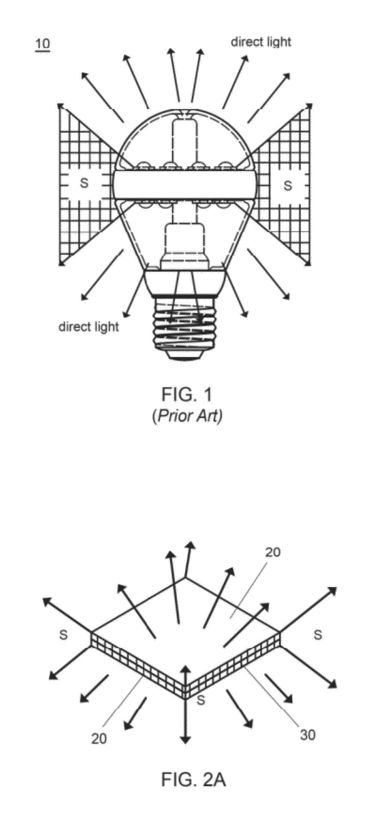
Despite the fact that side-view LEDs may be utilized to cover the lateral illumination as shown in FIGS. 2˜6 of the '529 patent, such implementation involving variations of types of LEDs may, however, potentially complicate the manufacturing processes and introduce inconsistencies to the preparation and selection of LEDs of appropriate beam codes in accordance with for example 1931 CIE Chromaticity Diagram.
One may evidently realize the benefits of the utilization of large area lighting devices or systems in the field of general lighting; however, there are still limitations to the implementation of such large area lighting sources.
One of the problems associated with such implementation of area lighting is clearly the amount of efforts and costs necessary for the replacement of existing systems and lighting fixtures in great scale.
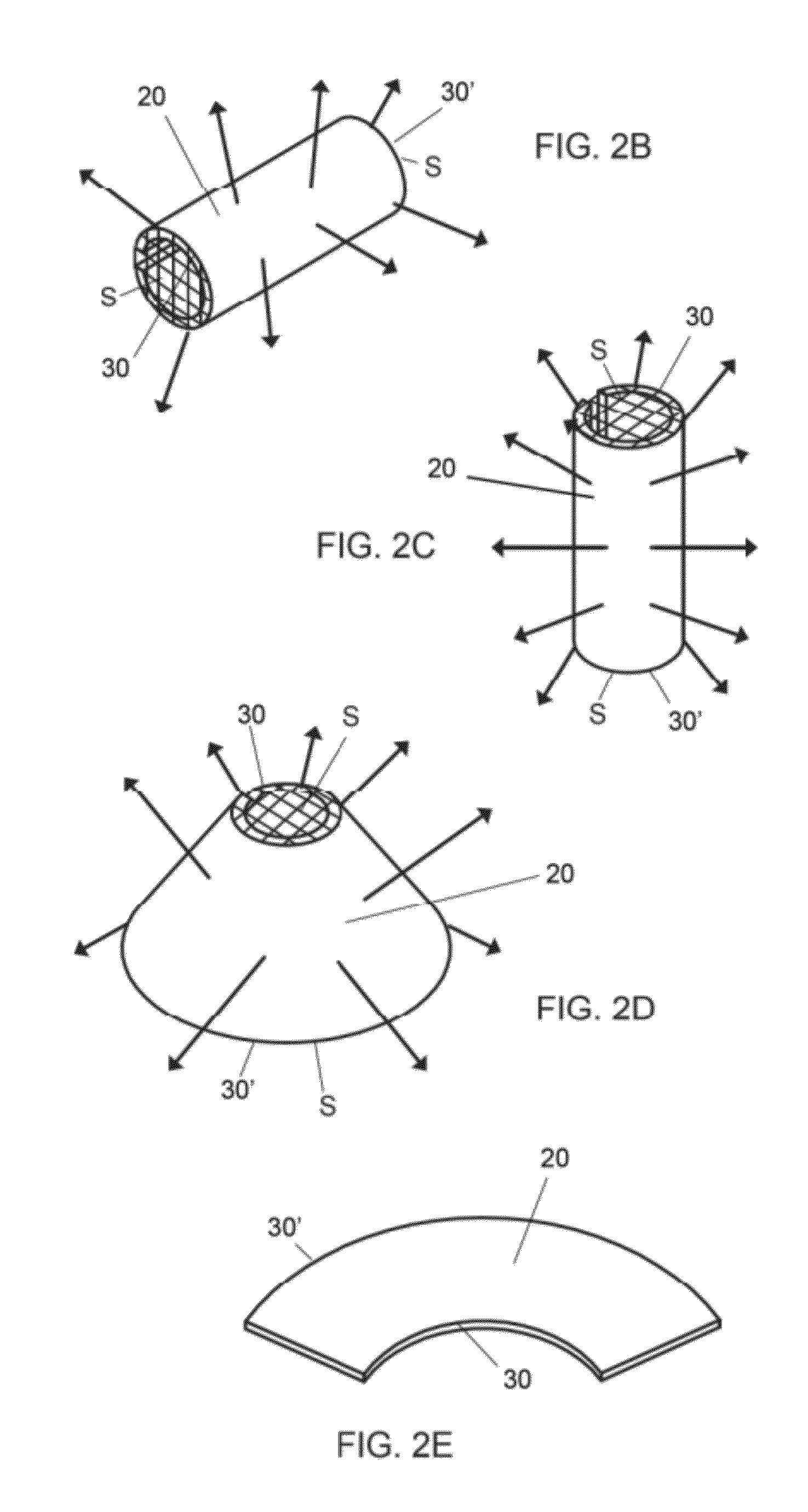
Another problem is also related to the limited illumination angles of light sheets since organic or inorganic LED light sheets in a planar form may still be of a limited illumination angle of 120˜140 degrees in general and with limited “direct lights” to the lateral sides, as shown in FIG. 2A.
For solid state lighting utilizing semiconductor materials, effective cooling of LEDs is necessary since both organic and inorganic LEDs are sensitive to the increase of operating temperature; as larger current input may advantageously lead to a greater light output from the LED, but may too result in undesirable increases of the operating temperature of the LED, causing degradation of LED performance and lifetime.

Method used


Image

  • LED light bulb having an LED light engine with illuminated curved surfaces
  • LED light bulb having an LED light engine with illuminated curved surfaces
  • LED light bulb having an LED light engine with illuminated curved surfaces

Examples


Embodiment Construction

[0041]An LED light bulb of the present invention is compatible with existing sockets for incandescent, filament or fluorescent light bulb and utilizes LED light sheets to provide direct lights in multiple directions projected outwardly from the LED light bulb. It may be preferable that the direct lights of an LED light engine of the LED light bulb of the present invention may be emitted or projected to at least six different sides of illumination zones of the LED light bulb such that a substantially spherical illumination may be obtained or achieved without excess use of reflective means. It may too be preferable that the structure of the LED light bulb of the present invention facilitates or enhances the cooling of the LED light engine without excess use of moving parts.

[0042]FIGS. 2A˜2E show some examples of LED light sheets having certain limitations in the illumination angles and in the feasibility of application as an LED light source or engine. As previously mentioned, FIG. 2A...


PUM


Abstract

The present invention relates to an LED light bulb utilizing LED light sheets with illuminated curved surfaces and can be used as a replacement bulb. The LED light bulb comprises an LED light engine having first and second LED modules with first and second illuminated curved surfaces facing toward different illumination zones I1, I2 respectively and attached to a thermally conducive support block with an increased curved surface area for heat dissipation. Said first and second illuminated curved surfaces are curved about first and second axes A, B respectively and are arranged to be offset from each other with said axes A and B substantially perpendicular to each other such that an improved illumination with direct lights shone to at least six different sides of the light bulb and subsequently a substantially spherical illumination of dispersed lights may be obtained along with an enhanced cooling of the light bulb.

Description

FIELD OF THE INVENTION[0001]The present invention relates to a lighting apparatus and more particularly, to a light emitting diode (LED) light bulb utilizing either organic LED (OLED) or inorganic LED light sheets on an LED light engine to provide an improved illumination of the light bulb with direct lights shone to multiple directions and different illumination zones. The LED light bulb of the present invention may be used as a replacement of existing bulbs for both indoor and outdoor applications, such as retrofits for incandescent and fluorescent light bulbs.BACKGROUND OF THE INVENTION[0002]With the merits of being energy efficient and environmental friendly, LEDs are extensively used in various lighting applications including such as general lighting, backlights and signs. LED light bulbs intended to be used as replacement bulbs of traditional light sources including incandescent and fluorescent lamps are too becoming widely available. Typical LED light bulbs utilizing inorgani...

Claims


Application Information

Patent Timeline
Patent Type & Authority Patents(United States)
IPC IPC(8): H01J61/52F21V29/00F21V7/20F21V29/505
CPCF21K9/135F21Y2101/02F21V3/00F21K9/232F21Y2115/10
Inventor SU, ALLEN HUI LONG
Owner SU ALLEN HUI LONG
Learn More