

Vision Correction Device And Method For Vision Correction
- Summary
- Abstract
- Description
- Claims
- Application Information
AI Technical Summary
Benefits of technology
Problems solved by technology
Method used
Image

Examples
second embodiment
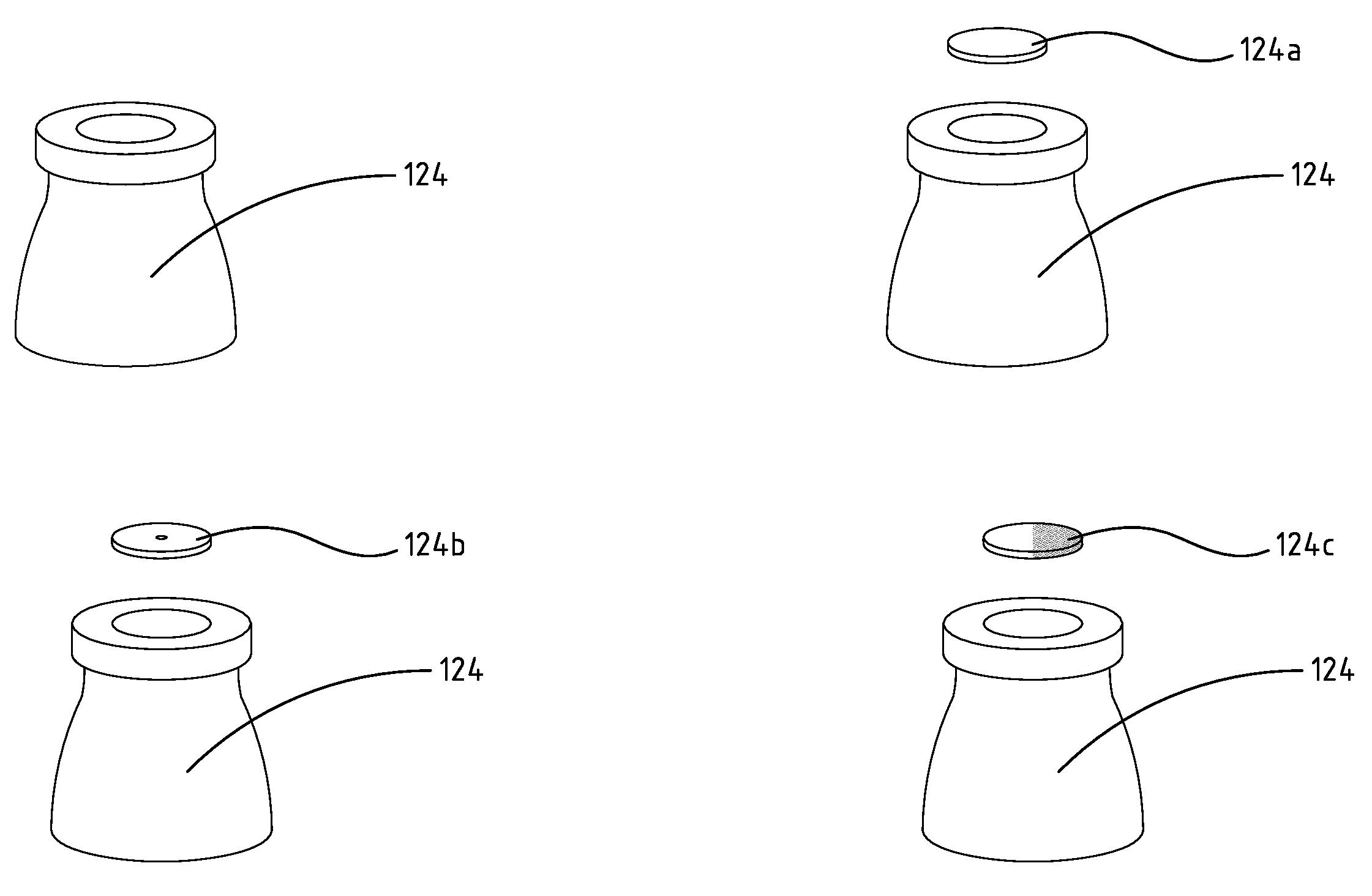
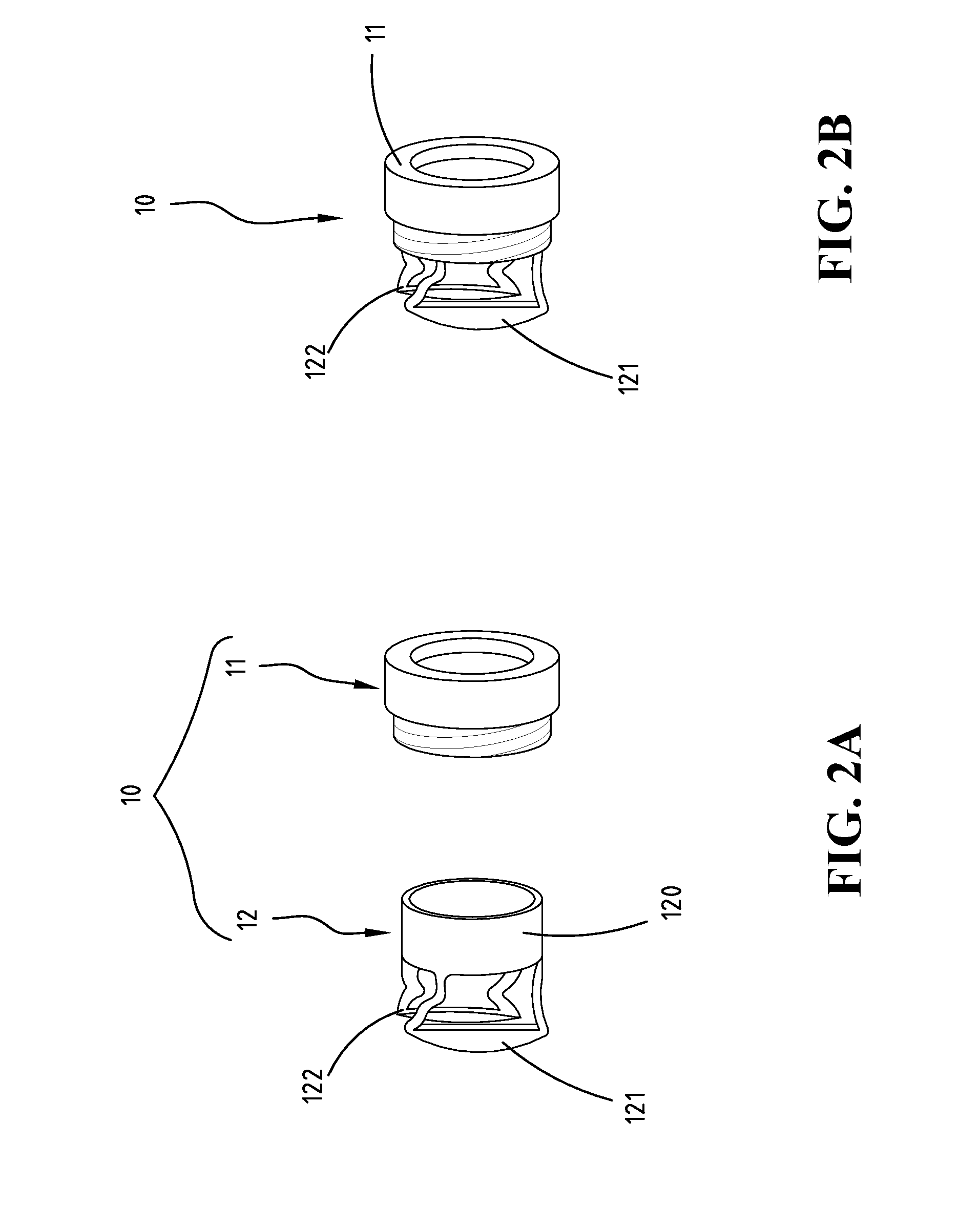
[0044]Referring to FIGS. 4A, 4B and 4C, a vision correction device 10 according to the present invention comprises a mount 11 shaped into a hollow cylinder and a correction part 12. The mount 11 includes a conjunction part 110 disposed therein. The correction part 12 comprises a correction base 120, a first pad 121, a second pad 122, a correction ring 124 and a correction ring hoop 123. The first pad 121 and the second pad 122 are disposed on the correction base 120. The correction ring hoop 123 is disposed on the correction base 120 and between the first pad 121 and the second pad 122. The correction ring 124 is telescoped into the correction ring hoop 123. The correction base 120 of the correction part 12 is telescoped into the conjunction part 110 of the mount 11. As shown in FIG. 4B, the first pad 121 and the second pad 122 press on the lower eyelid and the upper eyelid, respectively. The first pad 121, the second pad 122, and the correction ring hoop 123 are made of an elastic ...
third embodiment
[0045]Referring to FIGS. 5A and 5B, a vision correction device 10 in accordance with the present invention comprises a mount 11 shaped into a hollow cylinder and a correction part 12. The mount 11 has a conjunction part 110 and a lens module 111 disposed therein. The correction part 12 comprises a correction base 120, a first pad 121 and a second pad 122. The first pad 121 and the second pad 122 are disposed on the correction base 120. The correction base 120 of the correction part 12 is telescoped into the conjunction part 110 of the mount 11. As shown in FIG. 5B, the first pad 121 and the second pad 122 press on the lower eyelid and the upper eyelid, respectively. The correction part 12 is made of an elastic material. The sections connecting the first pad 121 and the second pad 122 with the correction base 120 are deformed when the pressure applied on the eyes is too high. Therefore the pressure applied on the eyes is relieved. This deformation mechanism prevents the eyes from bei...
fourth embodiment
[0046]Referring to FIGS. 6A and 6B, a vision correction device 10 according to the present invention comprises a mount 11 shaped into a hollow cylinder and a correction part 12. The mount 11 includes a conjunction part 110 and an illuminant 112 disposed therein. The correction part 12 comprises a correction base 120, a first pad 121 and a second pad 122. The first pad 121 and the second pad 122 are disposed on the correction base 120. The correction base 120 of the correction part 12 is telescoped into the conjunction part 110 of the mount 11. As shown in FIG. 6B, the first pad 121 and the second pad 122 press on the lower eyelid and the upper eyelid, respectively. The correction part 12 is made of an elastic material. The sections connecting the first pad 121 and the second pad 122 with the correction base 120 are deformed when the pressure applied on the eyes is too high. Therefore the pressure applied on the eyes is relieved. This deformation mechanism prevents the eyes from bein...
PUM
 Abstract
Description
Claims
Application Information