Power management system and method

a technology of power management system and computing device, applied in the direction of energy consumption reduction, sustainable buildings, high-level techniques, etc., can solve the problems of not having been programmed in a manner, not knowing when to transition from high-power state to low-power state, and optimizing power consumption for computer devices

Inactive Publication Date: 2008-04-24
G2 MICROSYST
View PDF14 Cites 27 Cited by
  • Summary
  • Abstract
  • Description
  • Claims
  • Application Information

AI Technical Summary

Benefits of technology

[0008] Power management for a computing device is described based on idle thread code execution and other conditions. In one example, a controller is operated at a first power state. Then the controller is transitioned from the first power state to a second lower power state after it starts executing idle thread code. As an additional optional feature it may be determined whether any one or more of a plurality of conditions is true and the controller may be transitioned from the first power state to the second power state if one or more of the plurality of conditions is true.

Problems solved by technology

Knowing when to transition from the high-power state to the lowest-power state is often an inefficient process.
The application may not have been programmed in a manner which optimizes power consumption for the computer device.
As a result, many computer devices are late to, or fail to, take advantage of opportunities in which it is possible to transition from a high-power state (such as active mode of operation) to a state of operation in which less power is consumed.

Method used


Image

  • Power management system and method
  • Power management system and method
  • Power management system and method

Examples


example method

of Operation

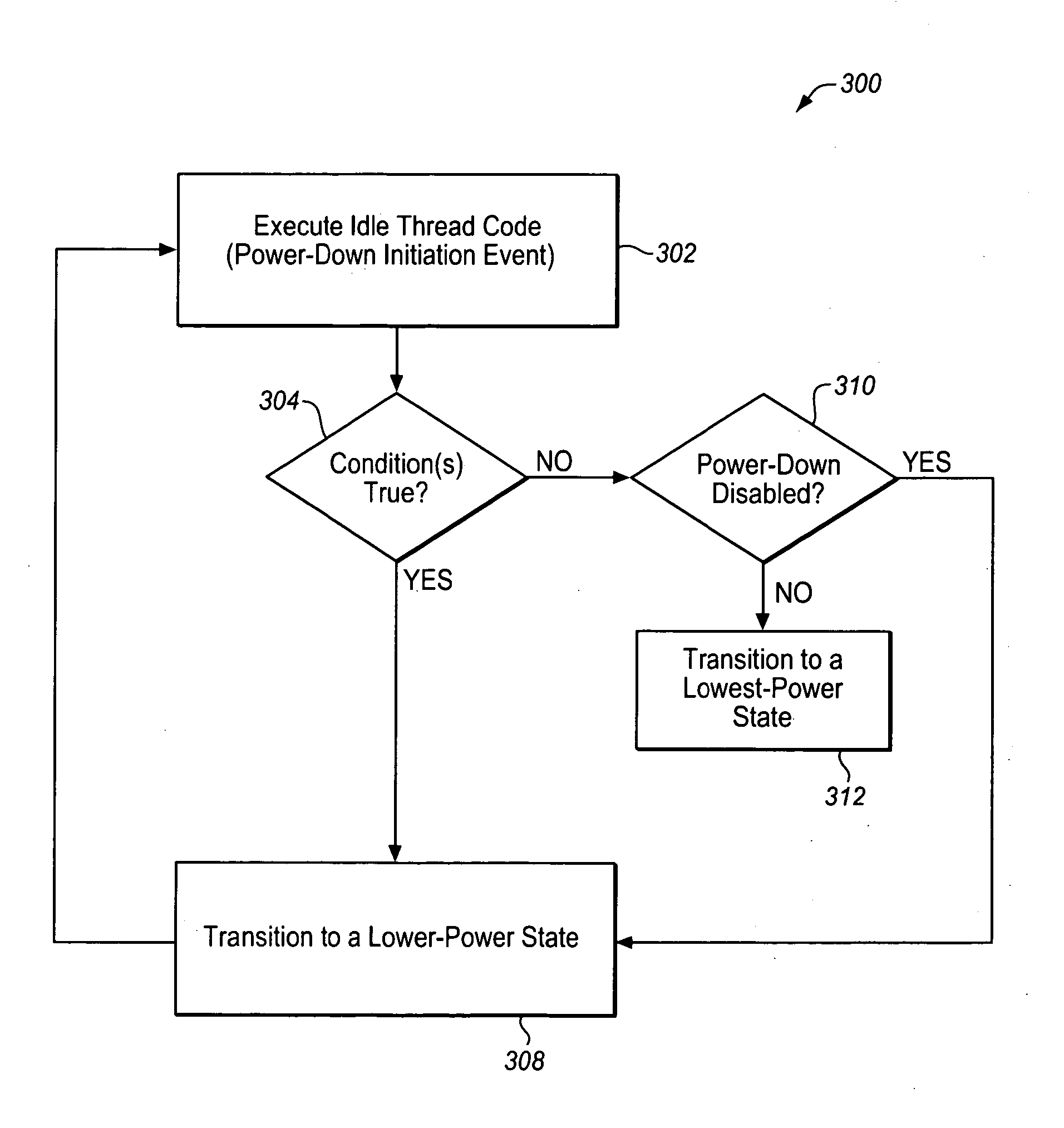
[0037]FIG. 3 illustrates an example method 300 for conserving power in a computing device, such as device 100 of FIG. 1. Method 300 includes blocks 302, 304, 306, 308, 310, and 312 (each of the blocks represents one or more operational acts). The order in which the method is described is not to be construed as a limitation, and any number of the described method blocks can be combined in any order to implement the method. Furthermore, the method can be implemented in any suitable hardware, software, firmware, or combination thereof. Additionally, although each module in FIG. 3 is shown as a single block, it is understood that when actually implemented in the form of computer-executable instructions, logic, firmware, and / or hardware, that the functionality described with reference to it may not exist as a separate identifiable block.

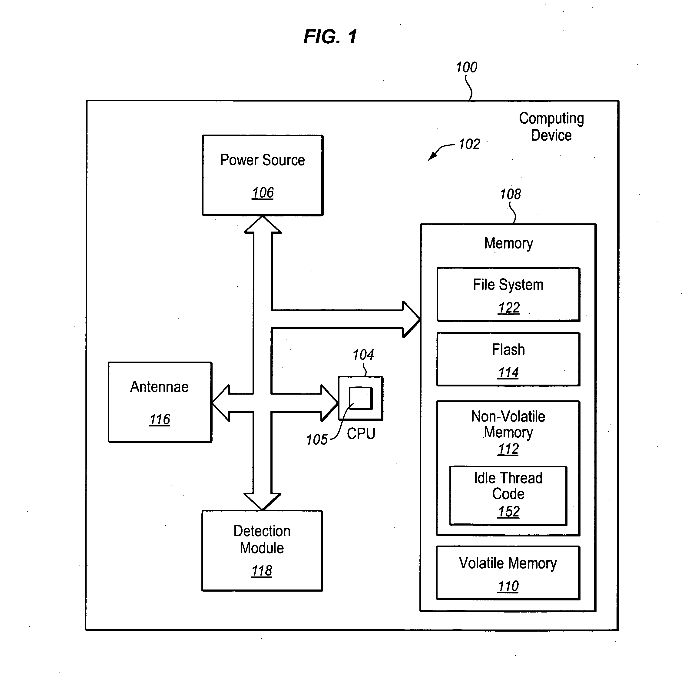
[0038] Referring to FIG. 3, in block 302 idle thread code is executed. For example, in one embodiment idle thread code 152 (FIGS. 1 and 2) f...


PUM


Abstract

Power management for a computing device is described based on idle thread code execution and other conditions. In one example, a controller is operated at a first power state. Then the controller is transitioned from the first power state to a second lower power state after it starts executing idle thread code. As an additional optional feature it may be determined whether any one or more of a plurality of conditions is true and the controller may be transitioned from the first power state to the second power state if one or more of the plurality of conditions is true.

Description

CROSS-REFERENCE TO RELATED APPLICATIONS [0001] This non-provisional application claims the benefit of earlier filed provisional application 60 / 785,009, filed Mar. 22, 2006, and entitled “Power Management System and Method”, the entirety of which is hereby incorporated by reference.BACKGROUND [0002] 1. Field [0003] This description relates generally to a power management system for a computing device, and in particular to managing power based on idle thread code execution and other conditions. [0004] 2. Related Art [0005] Many computing devices use electrical energy from a limited source of power resident with the device, such as a battery. Conserving power in devices with a finite amount of power is a paramount concern. Attempts are being made to extend the ability of these devices to operate without exhausting their supply of power. Semi-passive and active Radio Frequency Identification (RFID) tags are examples of one type of computing device with limited sources of power. Such tag...

Claims


Application Information

Patent Timeline
Patent Type & Authority Applications(United States)
IPC IPC(8): G06F1/00
CPCY02B60/1278G06F1/3287Y02B60/32Y02B60/1282G06F1/3203Y02D10/00Y02D30/50
Inventor HOGAN, MICHAEL T.MCDERMOTT, THOMAS
Owner G2 MICROSYST
Why Eureka
Try Eureka