Print Head Cleaning

a print head and cleaning technology, applied in printing and other directions, can solve the problems of print head dysfunction, nozzle or filter blockage in the channel, and dried ink can produce particles causing print defects,

Active Publication Date: 2008-05-01
MARKEM IMAJE HLDG
View PDF16 Cites 25 Cited by
  • Summary
  • Abstract
  • Description
  • Claims
  • Application Information

AI Technical Summary

Problems solved by technology

Indeed, dried ink can produce particles causing print defects; the nozzles or filters in the channels can also become blocked.
Above all, dried ink alters the values of the channel effective cross-sections, possibly until they are totally obstructed, causing a dysfunction of the print head, or even a malfunction, due to a change to and / or disturbance of the jet.
These transitions lead to directional instability of the jet leaving the nozzle, which requires complex compromises and changes to the shape and configuration of the nozzle, causing problems in the definition of this element which is essential for good printing.
In addition, the soiling caused by this ink leads to a dysfunction of any of the electrodes; a short-circuit may even occur in some cases.

Method used


Image

  • Print Head Cleaning
  • Print Head Cleaning
  • Print Head Cleaning

Examples


Embodiment Construction

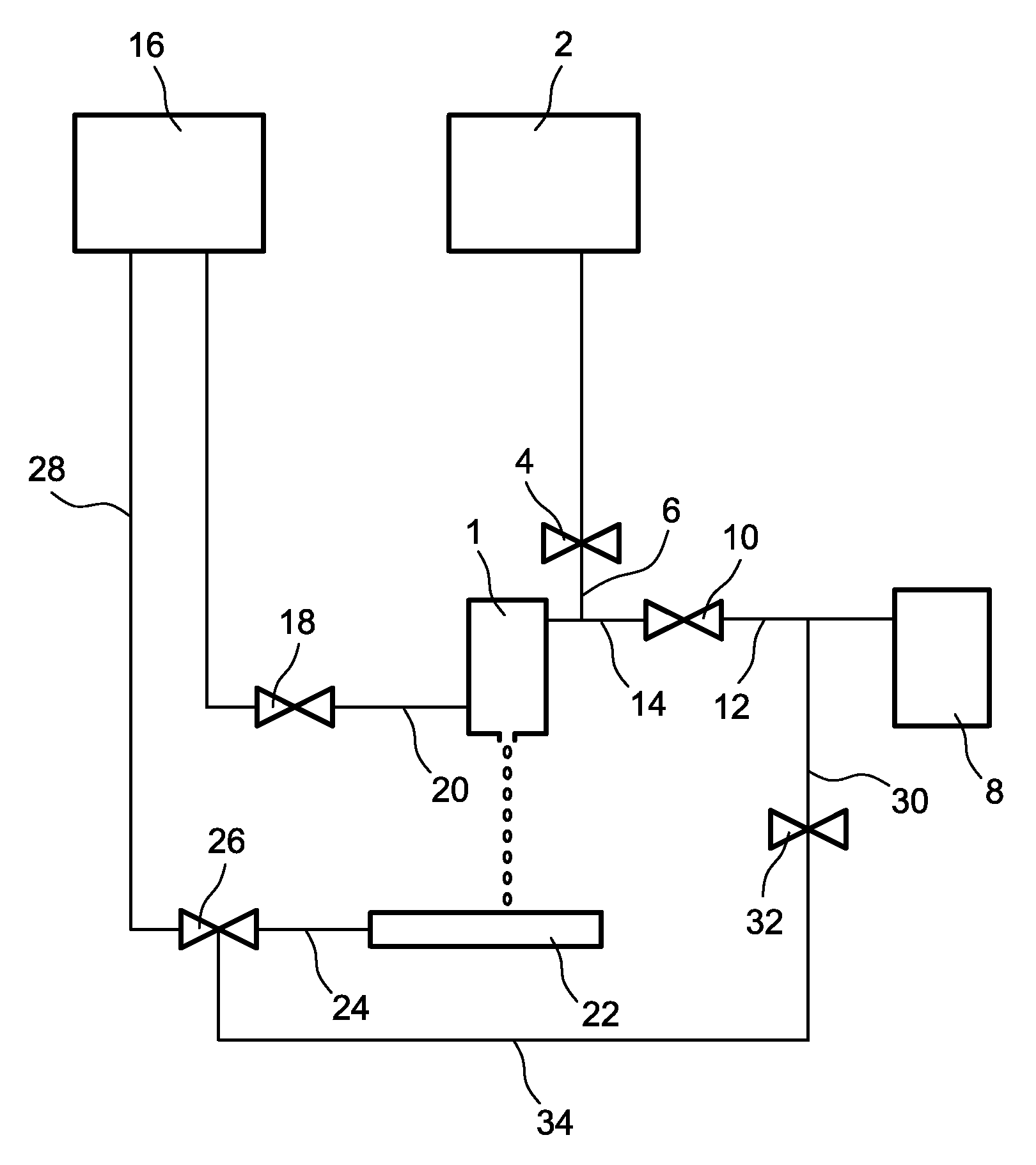
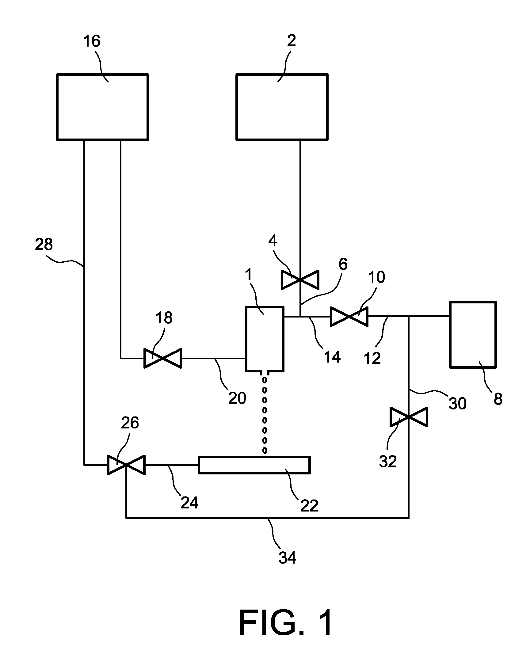
[0016]The invention aims to overcome these risks of instability of the jet during ink-solvent-ink transitions, while properly cleaning all of the conduits and the gun.

[0017]In one embodiment, the invention relates to a method for cleaning the ink passing through the conduits, a gun and a collection gutter of a print head, which has the advantages of simplicity of the aforementioned patent application, while preventing the spray of solvent from the nozzle. In particular, there is no ink-solvent-ink transition since the gun projects only ink and never solvent.

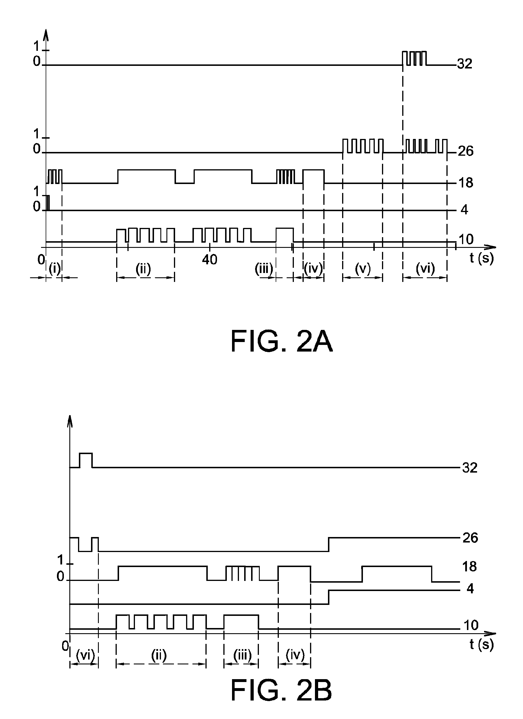
[0018]More specifically, the invention relates to a method for cleaning a print head of an ink jet printer comprising an ink gun, connected, by means of devices capable of being controlled, to an ink chamber, a solvent chamber and a vacuum source. The method according to the invention comprises, after a print phase, the following steps:[0019](1) interruption of a hydraulic connection between the gun and the ink chamber, so that t...


PUM


Abstract

To clean a print head of an ink jet printer comprising an ink gun (1), connected, by means of devices capable of being controlled, to an ink chamber (2), a solvent chamber (8), a vacuum source (16), and an ink collection gutter (22) capable of being connected in a controlled manner to a vacuum source (16), the following steps are performed:
    • (1) an interruption of a hydraulic connection between the gun (1) and the ink chamber (2) is ordered,
    • (2) the gun (1) is connected to the vacuum source (16),
    • (3) the solvent chamber (8) is hydraulically connected to the vacuum source (16) via a circuit (12, 14, 20) comprising the ink gun (1).

Description

TECHNICAL FIELD[0001]This invention relates to the field of cleaning print heads of ink jet printers. More specifically, the invention relates to a method for cleaning for a continuous jet printer as well as a print head suitable for this method.PRIOR ART[0002]The typical operation of a continuous jet printer can be described as follows. Electrically-conductive ink is held under pressure in an ink gun which is part of a print head comprising a body. The ink gun consists of a chamber intended to contain ink to be stimulated, and a recess for a device for periodic stimulation of the ink, for example, a piezoelectric actuator, among others the stimulation chamber comprises, from the inside to the outside, at least one passage for carrying ink to a calibrated nozzle, formed in a nozzle plate. The pressurized ink is discharged from the nozzle, thus forming an ink jet.[0003]The periodic stimulation device housed in the ink gun causes the ink jet to break up at regular time intervals at a ...

Claims


Application Information

Patent Timeline
Patent Type & Authority Applications(United States)
IPC IPC(8): B41J2/165
CPCB41J2/16532B41J2/185B41J2/16552
Inventor PERRIN, MAXCHALAMET, DANIEL
Owner MARKEM IMAJE HLDG
Why Eureka
Try Eureka