Method for setting a wheel torque in a vehicle

Active Publication Date: 2011-12-01
ROBERT BOSCH GMBH
View PDF7 Cites 6 Cited by
  • Summary
  • Abstract
  • Description
  • Claims
  • Application Information

AI Technical Summary

Benefits of technology

[0016]According to a preferred implementation, a torque is applied to the wheels on the rear axle which ensures the stability of the rear wheels. A corresponding torque redistribution takes place between the front and the rear axles, this intervention normally not being perceptible to the

Problems solved by technology

Ascertaining the latter exactly i

Method used


Image

  • Method for setting a wheel torque in a vehicle
  • Method for setting a wheel torque in a vehicle
  • Method for setting a wheel torque in a vehicle

Examples


Embodiment Construction

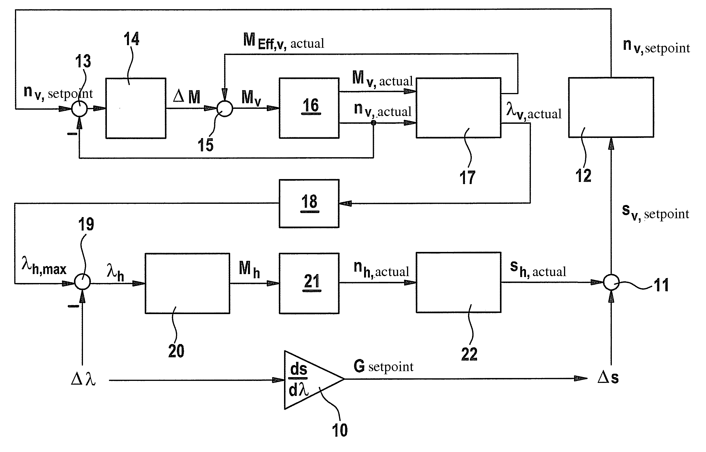
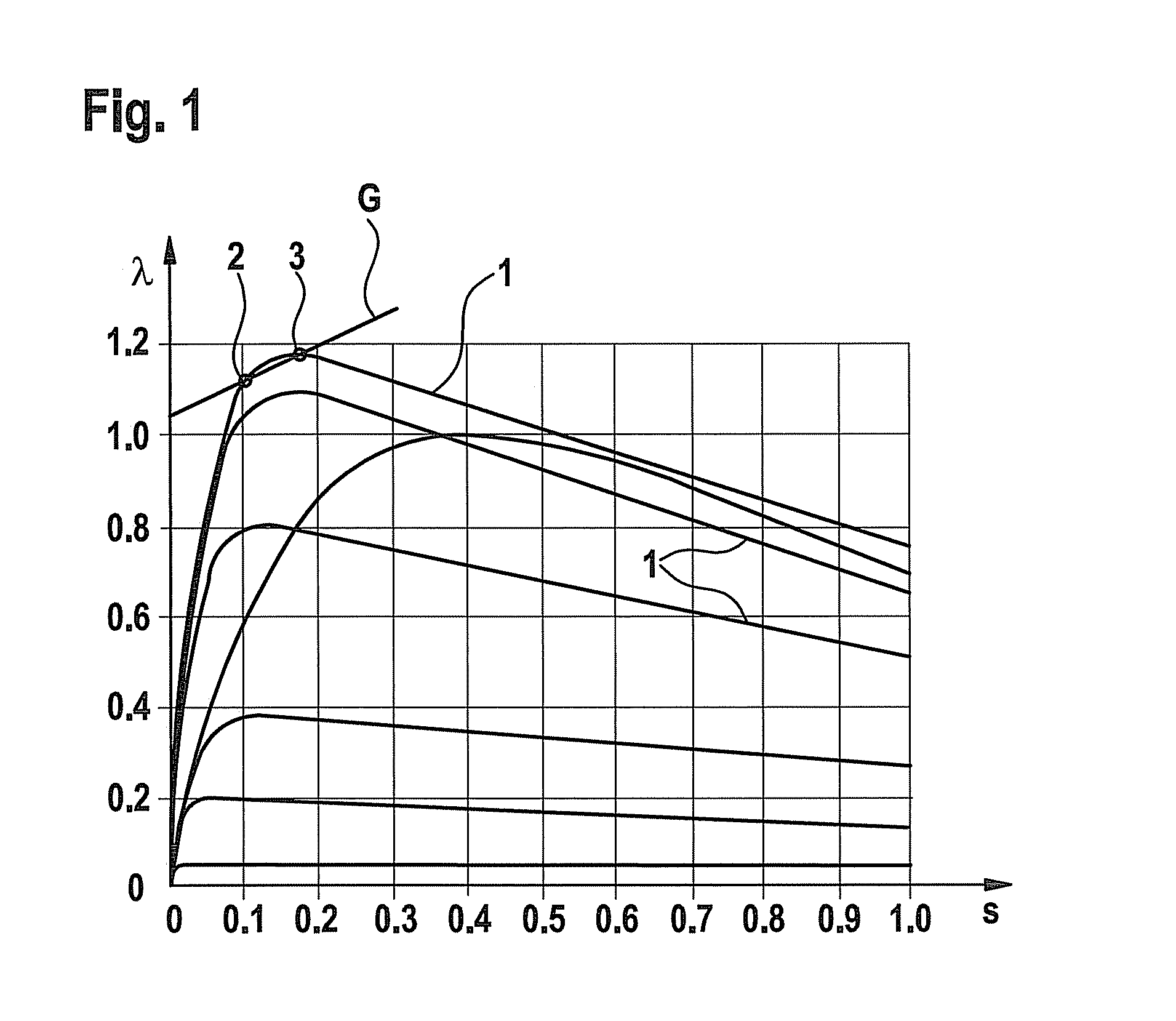
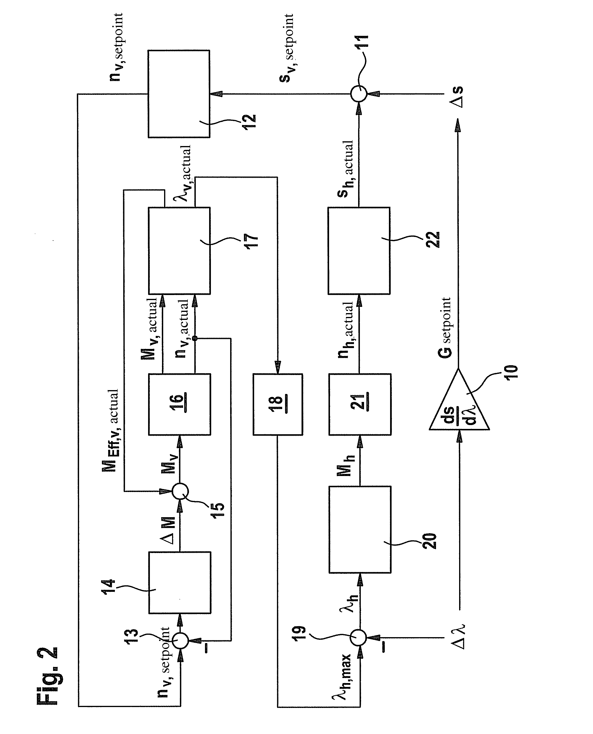
[0020]FIG. 1 depicts a slip-adhesion coefficient diagram, having a multitude of curves 1 which depict the correlation between adhesion coefficient λ and slip s at a vehicle wheel for various undersurfaces or road conditions. Adhesion coefficient λ designates the quotient of longitudinal force to vertical force at the vehicle wheel in question. The lower curves in FIG. 1 apply to lower friction coefficients, for example under snowy or icy conditions; the higher curve patterns on the other hand apply to higher friction coefficients. The uppermost curve 1 applies to a dry road surface.

[0021]For example, in the area of the maximum of the uppermost curve 1 a gradient G is laid out which is defined as a straight line through two points 2 and 3, of which point 2 is located on the rear wheel and point 3 on the front wheel, with corresponding values for slip s and adhesion coefficient λ. Point 2 on the rear wheel lies before the maximum of curve 1; point 3 on the front wheel on the other han...


PUM


Abstract

In a method for setting a wheel torque in a vehicle, a setpoint value for a slip-adhesion coefficient gradient for one wheel of one vehicle axle is ascertained, and the wheel torque is set in such a way that the actual value of the gradient is approximated to the setpoint value.

Description

BACKGROUND INFORMATION[0001]Driver assistance systems such as anti-lock braking systems (ABS) or anti-slip regulation systems (ASR) are known, via which an intervention may be performed in the vehicle to influence the driving dynamics, independent of the driver. In this case, braking or drive torques at one or more wheels of a vehicle are set to a predefined setpoint value. Precise regulation usually requires exact knowledge of a reference velocity of the vehicle, in order to be able to determine the current actual slip at the vehicle wheels. Ascertaining the reference velocity with high precision is relatively complicated, however; furthermore, determining the reference velocity during a braking process in which the anti-lock braking system is activated, or in the case of an anti-slip regulation system, in particular in vehicles with all-wheel drive, is relatively error-prone. Furthermore, determining the desired setpoint slip on various undersurfaces is a relatively complex proces...

Claims


Application Information

Patent Timeline
IPC IPC(8): B60K28/16G06F19/00B60W10/18B60W30/188
CPCB60K28/16B60T8/175B60T8/17616B60W10/04B60W2720/30B60W30/188B60W2520/10B60W2520/263B60W2720/26B60W10/18
Inventor BOEKER, RALPHTHOMYS, ADRIANWAGNER, OLIVERSTRAUSS, TOBIAS
Owner ROBERT BOSCH GMBH
Why Eureka
Try Eureka