Exhaust emission control device with additive injector

a technology of emission control device and additive, which is applied in the direction of engine components, mechanical equipment, machines/engines, etc., can solve the problems of unstable mixing of urea aqueous solution with exhaust gas homogeneously, intense heat of exhaust gas, etc., to minimize the transmission of intense heat of exhaust emissions, facilitate machining of protruding parts, and minimize the adhesion of additiv

Inactive Publication Date: 2008-07-03
DENSO CORP
View PDF15 Cites 55 Cited by
  • Summary
  • Abstract
  • Description
  • Claims
  • Application Information

AI Technical Summary

Benefits of technology

[0015]Specifically, the protrusion extends outside the exhaust pipe. The additive injector is retained by the protrusion without being exposed directly to the exhaust emissions flowing through the exhaust pipe, thereby minimizing the transmission of intense heat of the exhaust emissions to the additive injector. Additionally, the additive injector is also so held by the protrusion as to avoid the interference of the cone-shaped spray of the additive with at least the downstream edge of the opening that is a portion of the opening located farthest away from the additive injector. Further, the protrusion is formed to extend substantially parallel to the longitudinal center line of the straight section of the exhaust pipe. The additive injector is secured to the second end of the protrusion. In other words, the center axis of the cone-shaped spray, that is, a path along which the additive is sprayed from the additive injector is aligned with the longitudinal center line of the straight section of the exhaust pipe, thereby minimizing the adhesion of the additive to an inner wall of the protrusion and mixing the additive to the exhaust emissions homogeneously which are, then, carried to the catalyst.
[0016]In the preferred mode of the invention, the additive injector is so oriented by the protrusion as to avoid interference of the cone-shaped spray of additive with an entire edge of the opening of the protrusion.
[0017]The protrusion has a cylindrical inner wall, thereby facilitating machining of the protrusion and also minimizing the adhesion of the spray of additive thereto.
[0018]The additive injector has a head in which a spray hole is formed. The distance between the downstream edge of the opening of the protrusion and the head of the additive injector is so selected as a function of an angle of spread of the additive, as sprayed from the additive injector, as to avoid interference of the cone-shaped spray of the additive with the downstream edge of the opening of the protrusion.
[0019]The additive injector is oriented in alignment of an axis thereof with that of the straight section of the exhaust pipe, thereby resulting in a uniform distribution of the spray of additive over the straight section of the exhaust pipe and carrying a homogeneous mixture of the additive and the exhaust emissions to the catalyst.

Problems solved by technology

However, the urea solution injection valves, as disclosed in the above second and third publications, are so disposed as to be exposed inside the bend, so that they are subjected to intense heat of the exhaust gas.
This structure is, however, needed to select the length of the protrusion from the outer surface of the bend or regulate the angle of a cone-shaped spread of urea aqueous solution accurately in order to avoid the adhesion of a spray of the urea aqueous solution to an inner wall of the protrusion, which may result in instability in mixing the urea aqueous solution with the exhaust gas homogeneously.

Method used


Image

  • Exhaust emission control device with additive injector
  • Exhaust emission control device with additive injector
  • Exhaust emission control device with additive injector

Examples


Embodiment Construction

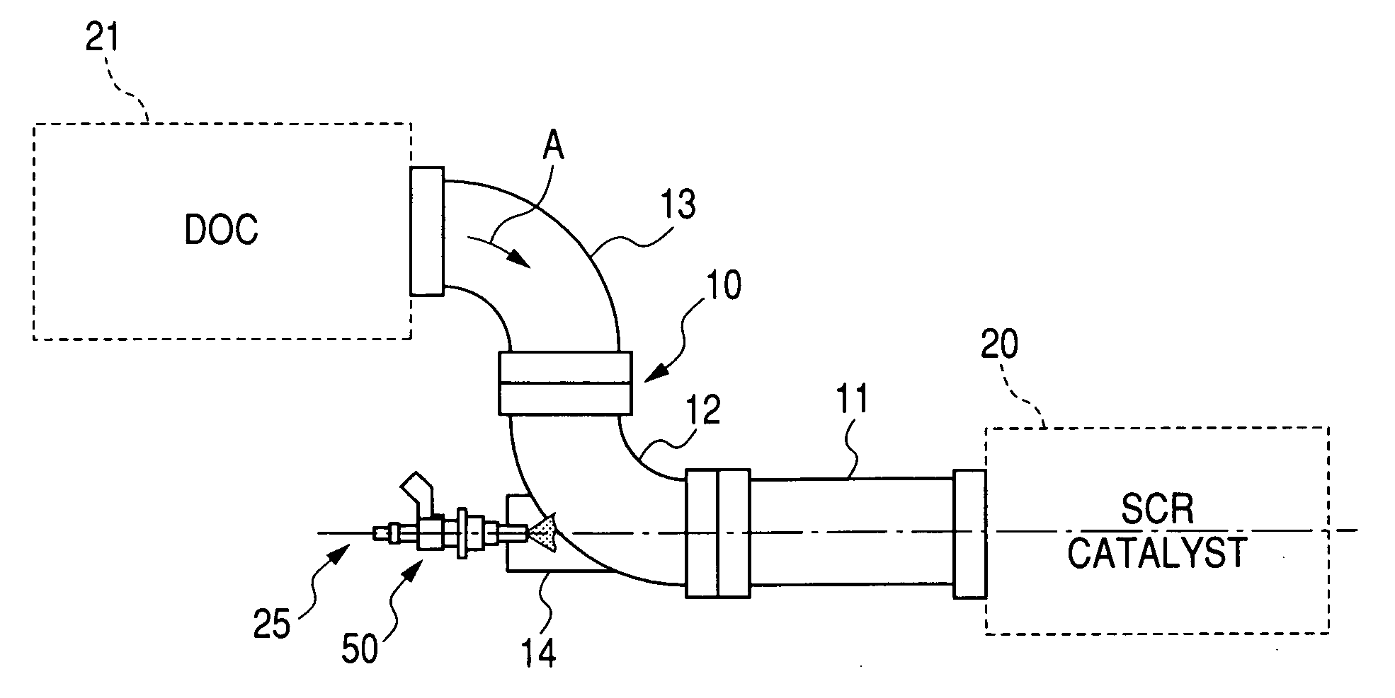
[0032]Referring to the drawings, particularly to FIG. 1, there is shown a urea SCR (Selectively Catalytic Reduction) system according to the invention which is engineered, like the one in FIG. 5, as an exhaust emission control device to convert NOx emissions contained in exhaust gas from an automotive diesel engine (not shown) into harmless products.

[0033]The urea SCR system includes a DOC (Diesel Oxidation Catalyst) 21, an exhaust pipe 10, and a SCR (Selectively Catalytic Reduction) catalyst 20, and a urea solution injection valve 50. The exhaust gas, as emitted from the diesel engine, flows through the exhaust pipe 10 in a direction A.

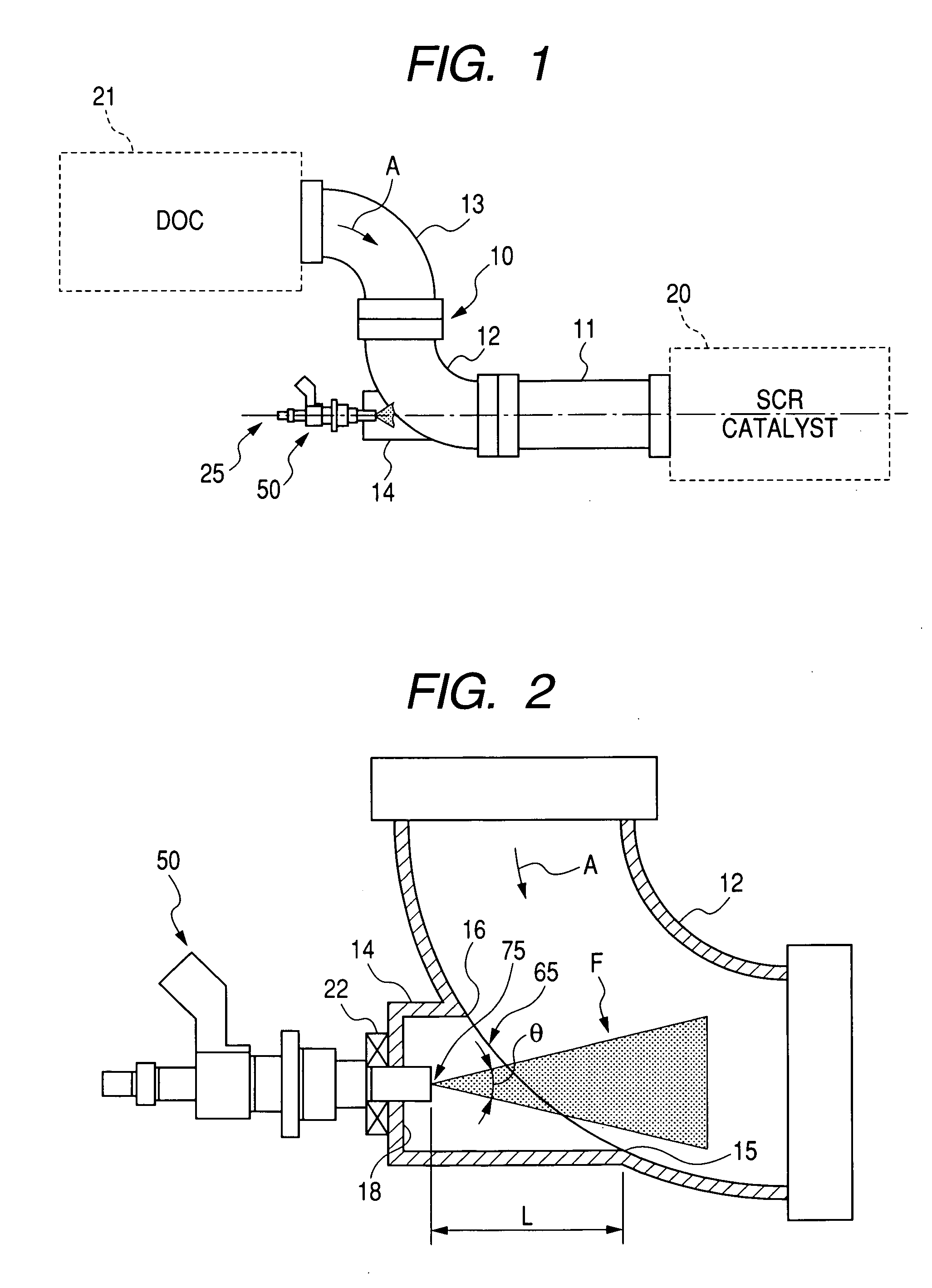
[0034]The urea solution injection valve 50 is installed in a portion the exhaust pipe 10 between the DOC 21 and the SCR catalyst 20. The urea solution injection valve 50 is controlled in operation by a controller (not shown) to inject or spray a urea aqueous solution as a reducing agent (also called reducer) to the exhaust gas flowing from the DOC 21...


PUM


Abstract

An exhaust emission control apparatus is provided which is equipped with an additive injector to inject additive such as a urea aqueous solution into an exhaust pipe through which exhaust emissions flow. The exhaust pipe includes a straight section and a bent section. A catalyst such as a SCR (Selective Catalytic Reduction) catalyst is disposed downstream of the straight section. A hollow protrusion is formed on an outer peripheral wall of the bent section substantially in parallel to a longitudinal center line of the straight section. The protrusion has an opening formed in one of opposed ends thereof which communicates with inside the bent section. The additive injector is designed to produce a cone-shaped spray of additive and installed on the other end of the protrusion to inject the cone-shaped spray of additive into the exhaust pipe without interfering with at least a downstream edge of the opening.

Description

CROSS REFERENCE TO RELATED DOCUMENT[0001]The present application claims the benefit of Japanese Patent Application No. 2006-342319 filed on Dec. 20, 2006, the disclosure of which is totally incorporated herein by reference.BACKGROUND OF THE INVENTION[0002]1. Technical Field of the Invention[0003]The present invention relates generally to an exhaust emission control device equipped with an additive injector which may be used with an SCR (Selective Catalytic Reduction) system working to induce an exhaust gas purification reaction using additive such as a urea aqueous solution.[0004]2. Background Art[0005]Urea SCR systems designed as exhaust emission control devices for use in electric power plants, factories, or automobiles especially equipped with diesel engines are now being developed and partially put in practical use.[0006]FIG. 5 illustrates a typical one of the urea SCR systems.[0007]The urea SCR system includes generally an SCR catalyst 51, an exhaust pipe 52 extending between a...

Claims


Application Information

Patent Timeline
Patent Type & Authority Applications(United States)
IPC IPC(8): F01N3/10
CPCF01N3/2066Y02T10/24F01N2610/02Y02A50/20Y02T10/12
Inventor MARUYAMA, MASATOSHIOHSHIMA, KEIJI
Owner DENSO CORP
Why Eureka
Try Eureka