

Reduced weight aircraft tire
a technology of aircraft tires and zigzag belt layers, which is applied in the field of pneumatic tires, can solve the problems that the tire designed with zigzag belt layers cannot carry as heavy a load as required by current commercial aircraft design requirements, and the crown area of pneumatic tires is flexed in a high degree, and the tire is particularly exacerbated
- Summary
- Abstract
- Description
- Claims
- Application Information
AI Technical Summary
Benefits of technology
Problems solved by technology
Method used
Image

Examples
first embodiment
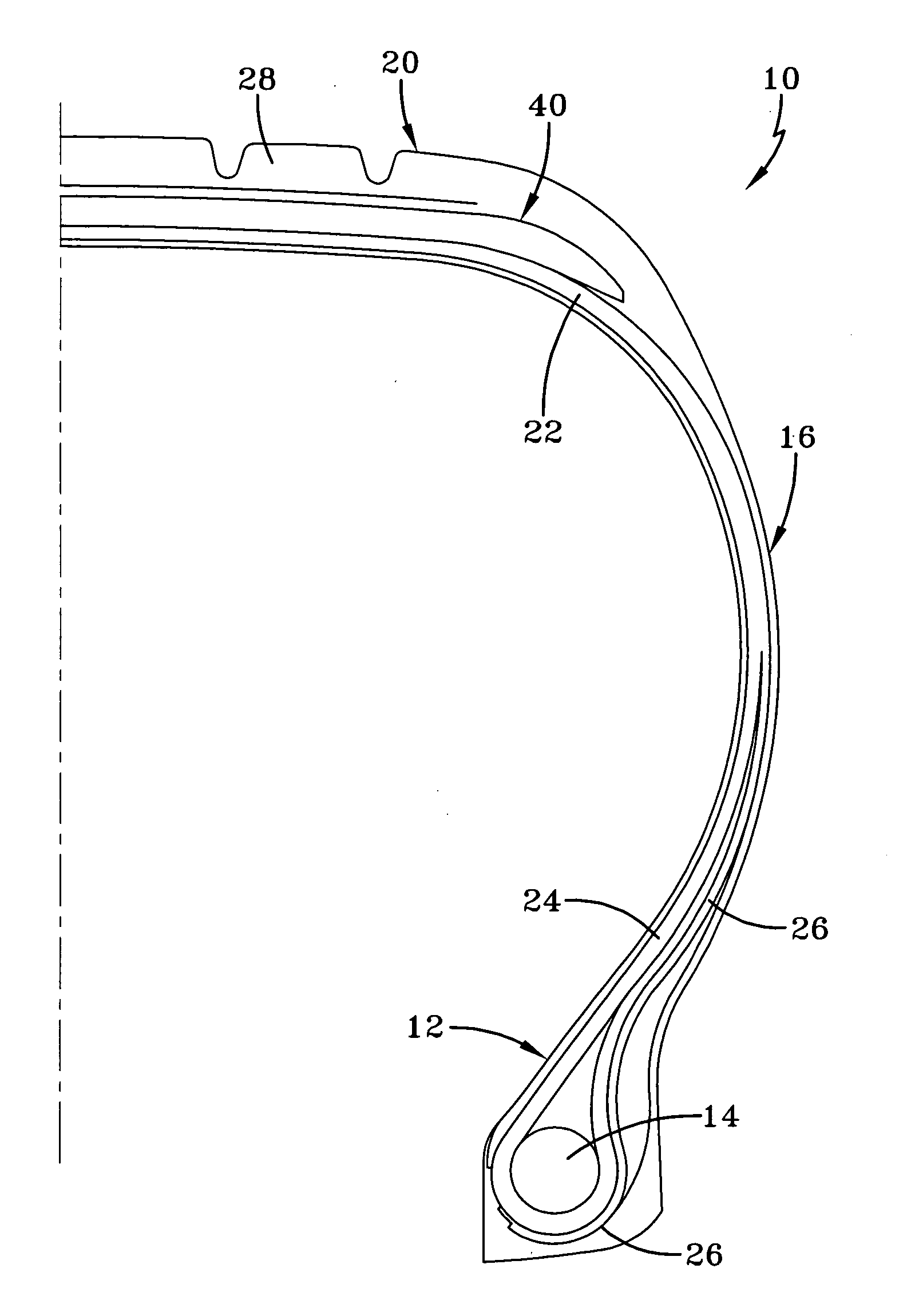
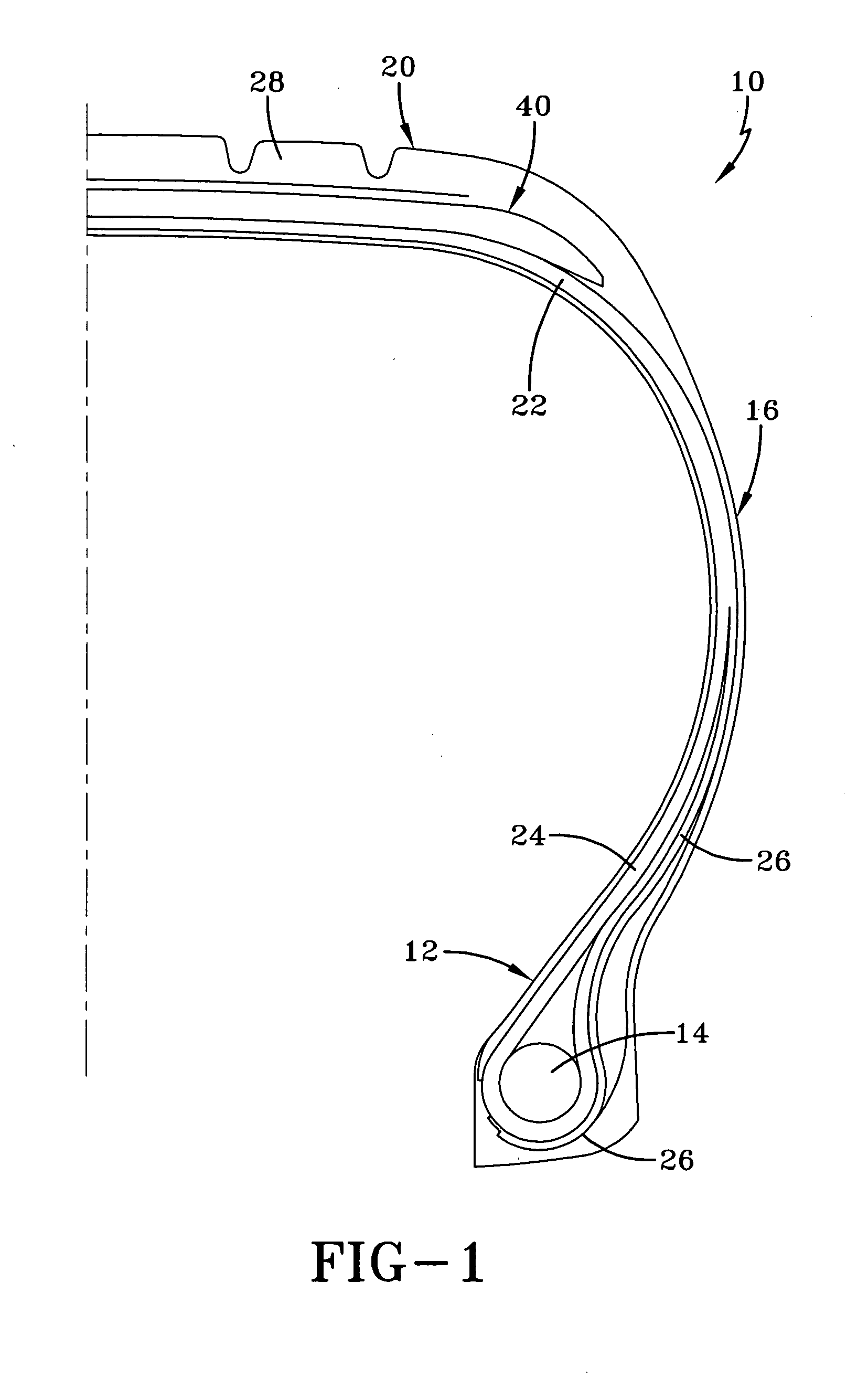
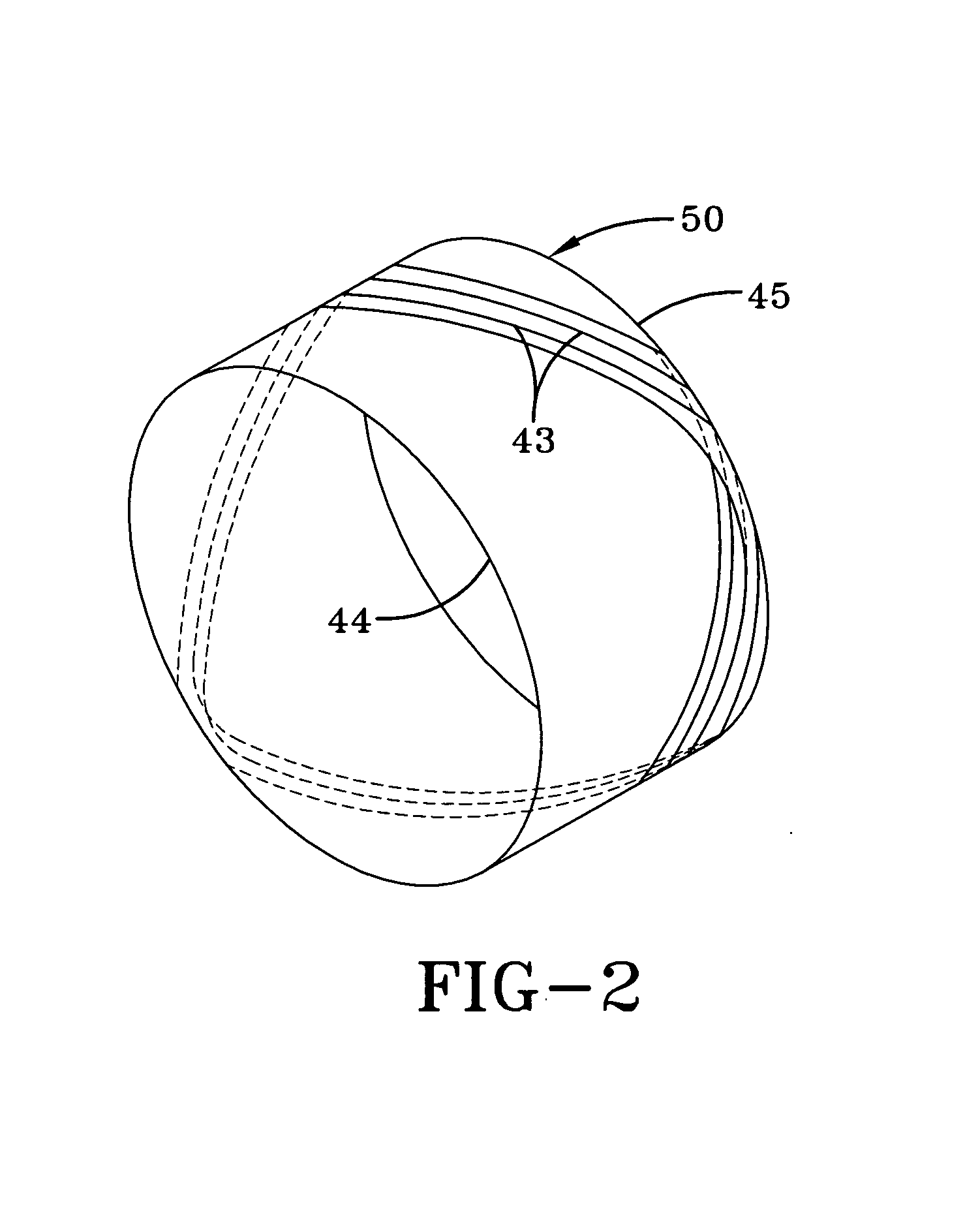
[0021]The aircraft tire 10 further comprises a belt package 40 arranged between the carcass 22 and the tread rubber 28. FIG. 3 illustrates a belt package 40 suitable for use in the aircraft tire. The belt package 40 as shown comprises a radially inner spirally wound belt layer 42 formed of cord or a rubberized strip 43 of two or more cords made by spirally winding the cords at an angle of plus or minus 5 degrees or less relative to the circumferential direction. Preferably, the belt package comprises two or more zero degree belt layers. The belt package 40 further comprises one or more zigzag belt reinforcing structures 50. Each zigzag belt reinforcing structure 50 is comprised of two layers of cord. The zigzag belt reinforcing structure is formed as shown in FIG. 2. A rubberized strip 43 of one or more cords 46, wound generally in the circumferential direction while being inclined to extend between side ends or lateral edges 44 and 45 of the layer forming a zigzag path as shown. Th...
second embodiment
[0025]FIG. 4 illustrates the present invention having two inner spirally wound layers 60,61, an inner zigzag structure 62 and two radially outer spirally wound belt layers 64, 66. The radially outer spiral layers 64, 66 may be wider than the zigzag belt structure 62. The outer spirally wound layers 64, 66 may be wider than the inner spiral layers 60, 61. The ratio of the zigzag belt width Wz to the widest spiral belt Ws width may be as follows:
0.6≦Wz / Ws1.0 (1)
[0026]More particularly, the ratio of the zigzag belt width Wz to the widest spiral belt width may be as follows:
0.5≦Wz / Ws0.98 (2)
[0027]FIG. 5 illustrates a third embodiment of the belt layer. FIG. 5 is similar to FIG. 4 in that the there are two inner spiral layers 70, 71, an inner zigzag structure 72 and two radially outer spirally wound belt layers 74, 76. In addition, the belt ends of the radially outer belt layers are wrapped around the zigzag belt structure. FIG. 5 differs from FIG. 4 in that the radially inner spiral l...
fourth embodiment
[0029]FIG. 6 illustrates the belt structure. FIG. 6 is similar to FIG. 5, having two radially inner spiral layers 70, 71, two radially outer spiral layers 74, 76. However FIG. 6 has two zigzag belt structures 78, 80 instead of one zigzag belt structure 78. The zigzag belt structures 78, 80 may be staggered in width, wherein the radially inner zigzag belt structure 78 is wider than the radially outer zigzag belt structure 80. The ratio of the zigzag belt width Wz to the widest spiral belt width may be as follows:
0.6≦Wz / Ws1.0 (1)
[0030]The ratio of the zigzag belt width Wz to the widest spiral belt width may also be as follows:
0.5≦Wz / Ws0.98 (2)
[0031]In any of the above described embodiments, the cord may be continuously wound from one layer to the next.
[0032]FIGS. 7 through 10 illustrate various starting and ending belt edge configurations for any of the spirally wound belt layers described above. In FIG. 7, the starting belt edge 80 and the ending belt edge 82 overlap near the cente...
PUM
| Property | Measurement | Unit |
|---|---|---|
| elongation at break | aaaaa | aaaaa |
| cord angles | aaaaa | aaaaa |
| cord angles | aaaaa | aaaaa |
Abstract
Description
Claims
Application Information