Hanging device for wireless transmission media

a wireless transmission media and hanging device technology, applied in lighting support devices, electrical apparatus casings/cabinets/drawers, instruments, etc., can solve the problems of general wireless transmission technology working, inconvenience during disengagement, unexpected fall of wireless transmission media from wall or ceiling surfaces, etc., to achieve convenient and easy stably retaining the hanging device, quick and stably retaining the wireless transmission media, and quick engagement

Inactive Publication Date: 2008-05-08
CAMEO COMM
View PDF10 Cites 14 Cited by
  • Summary
  • Abstract
  • Description
  • Claims
  • Application Information

AI Technical Summary

Benefits of technology

[0008]A primary object of the present invention is to provide a hanging device, which is provided with an engaging fastener and an engaging recess for engaging with each other, wherein the engaging fastener is formed with a rib to slide into a slide track of the engaging recess. When the rib of the engaging fastener is slid to an end along the slide track, a positioning recess formed on an upper surface of the engaging fastener will engage with a positioning projection of the engaging recess so as to be

Problems solved by technology

However, general wireless transmission technology works only when using wireless transmission media, such as a wireless router or a wireless access point, for linking to the Internet.
However, when some repair, function extension, or battery exchange is executed with respect to the wireless transmission media, a user must use hand tools to manually take the hanging device 1 of the wireless transmission media apart from the wall surface resulting in i

Method used


Image

  • Hanging device for wireless transmission media
  • Hanging device for wireless transmission media
  • Hanging device for wireless transmission media

Examples


Embodiment Construction

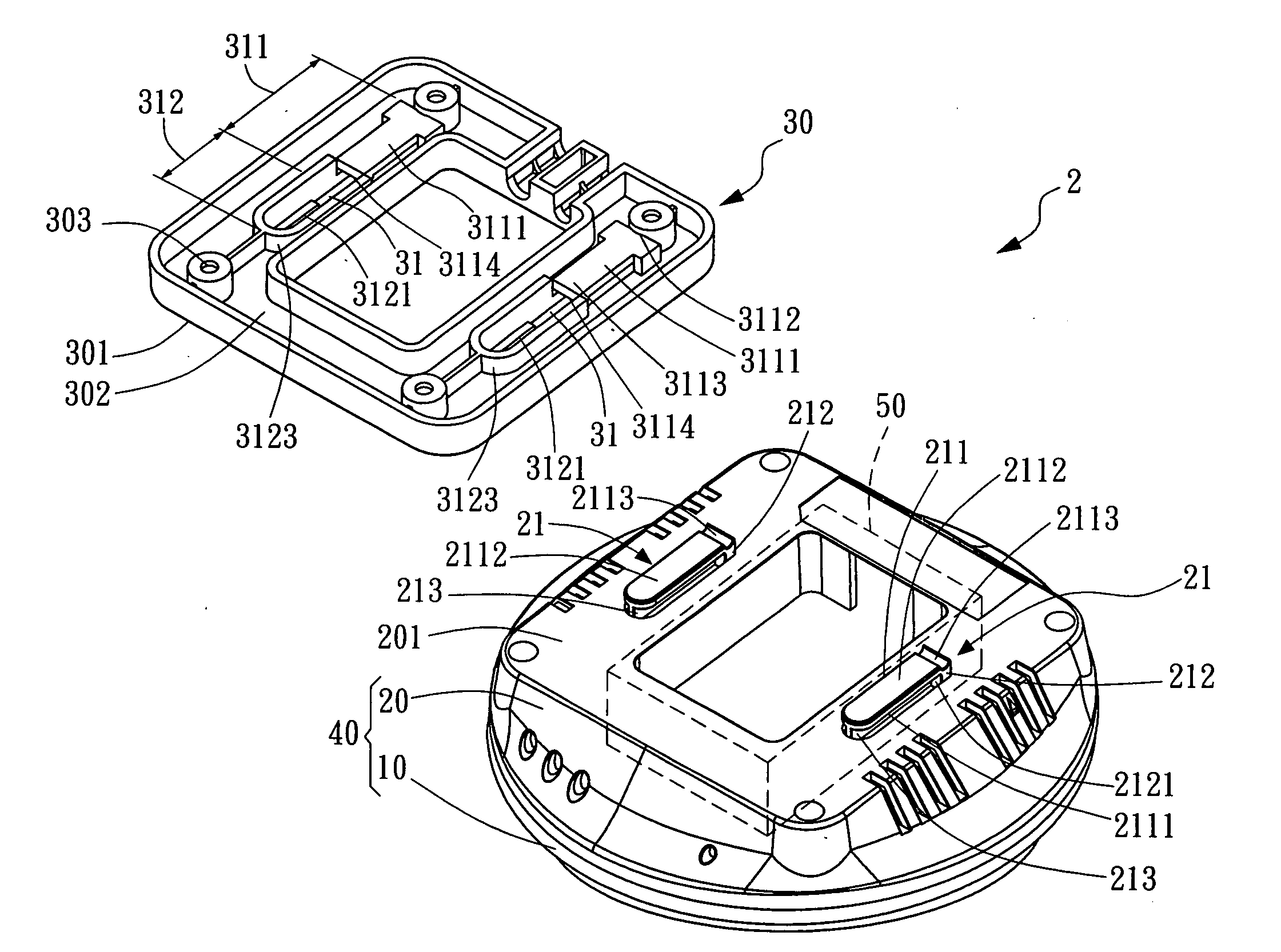
[0017]Referring now to FIG. 2, an exploded perspective view of a hanging device for a wireless transmission media according to a preferred embodiment of the present invention is illustrated. As shown, the hanging device designated by numeral 2 of the present invention comprises an upper housing 10, a lower housing 20, and a hanging base 30. The upper housing 10 can be connected with the lower housing 20 to constitute a hollow housing 40 in which a wireless transmission module 50 is received in a receiving space (unlabeled) formed between the upper housing 10 and the lower housing 20. The wireless transmission module 50 can be selected from the group comprising: wireless router, wireless IP sharing device, and wireless access point.

[0018]Referring still to FIG. 2, the lower housing 20 has a rear side 201 (also called a bottom side) opposite to a connecting side (unlabeled) which is used for connecting the upper housing 10, and the rear side 201 (bottom side) of the lower housing 20 i...


PUM


Abstract

A hanging device for a wireless transmission media comprising at least one engaging fastener formed on a housing of the wireless transmission media, and a hanging base. The engaging fastener shaped in an “L” configuration is provided with a sliding hook having a positioning recess formed on an upper surface thereof, a connecting portion, and a rib projected from a center portion of an inner surface of the sliding hook adjacent to the connecting portion. The hanging base is provided with at least one engaging recess which includes an inserting portion and a sliding portion, wherein the inserting portion has an elastically positioning piece and a positioning projection while the sliding portion has a slide track, a sliding opening, and a positioning frame. The sliding hook of the engaging fastener is used to insert into the inserting portion of the engaging recess, and elastically bias the elastically positioning piece formed on a bottom portion of the engaging recess so that the rib can be aligned with the sliding opening of the sliding portion, and then inserted into the slide track. When the rib of the engaging fastener is slid to an end along the slide track, the sliding hook is inserted into the positioning frame, and then the positioning recess will engage with the positioning projection so as to stably retain the engaging fastener in the engaging recess.

Description

BACKGROUND OF INVENTION[0001]1. Field of the Invention[0002]The present invention relates to a hanging device for a wireless transmission media, and more particularly to a hanging device comprising an engaging fastener formed on a lower housing of a housing of a wireless transmission media, and an engaging recess formed on a hanging base for engaging with each other so as to stably retain the wireless transmission media on a wall surface or a ceiling surface.[0003]2. Description of the Prior Art[0004]Due to advances in Internet-related information, methods for accessing the Internet not only include traditional wired transmission technology, but also novel wireless transmission technology, which is a new accessing trend based on the increasing needs of users. The wireless transmission technology is advantageous to reduce the unnecessary use of networking cables and to provide mobile internet access for more users so as to access the Internet without being limited by spatial barriers...

Claims


Application Information

Patent Timeline
IPC IPC(8): G06F1/16
CPCH05K5/0204
Inventor TU, KUO CHIANG
Owner CAMEO COMM
Why Eureka
Try Eureka