Power Saver Controller

a power saving controller and controller technology, applied in the direction of liquid/fluent solid measurement, instruments, sustainable buildings, etc., can solve the problems of large time consumption of computer operating systems, unsatisfactory, and inability to tolerate power removal from peripheral devices by computer systems. , to achieve the effect of simple and relatively time-consuming

Active Publication Date: 2008-05-08
EMBER TECH PTY LTD
View PDF4 Cites 43 Cited by
  • Summary
  • Abstract
  • Description
  • Claims
  • Application Information

AI Technical Summary

Benefits of technology

[0016]The modern desktop computer generally has a complex and relatively time consuming “power up sequence” which is the series of activities which the computer performs immediately upon being first switched on. This sequence may include activities to discover what peripheral devices are connected to the computer and to establish communication with such peripherals. One of the advantages of the standby mode is that it is not necessary for the computer to go through this power up sequence when it emerges from standby into fully powered mode.

Problems solved by technology

This is a time consuming process and indeed given the placement of the power switches on many such electrical devices, may be extremely inconvenient.
It is also the case that widely used computer operating systems require significant time to perform certain “housekeeping” tasks in between receiving command to shut down and actually shutting off the power or being in a position to have the power supply to the computer shut off without causing problems for the computer system.
During this time, the computer system also may not tolerate having power removed from peripheral devices.
This is not ideal for a number of reasons.
The first of these is that the devices continue to consume power which is both costly and a waste of resources.
This is particularly a problem since many modern devices use small plug-in transformers to provide the lower operating voltages which they require.
These plug-in transformers continue to consume power whilst they are connected to a mains supply even if the power switch on the device which they are supplying with power has been switched off.
Users may allow the device to spend extended periods in such a standby state, negating most of the advantages of the prior art devices.

Method used


Image

  • Power Saver Controller
  • Power Saver Controller
  • Power Saver Controller

Examples


Embodiment Construction

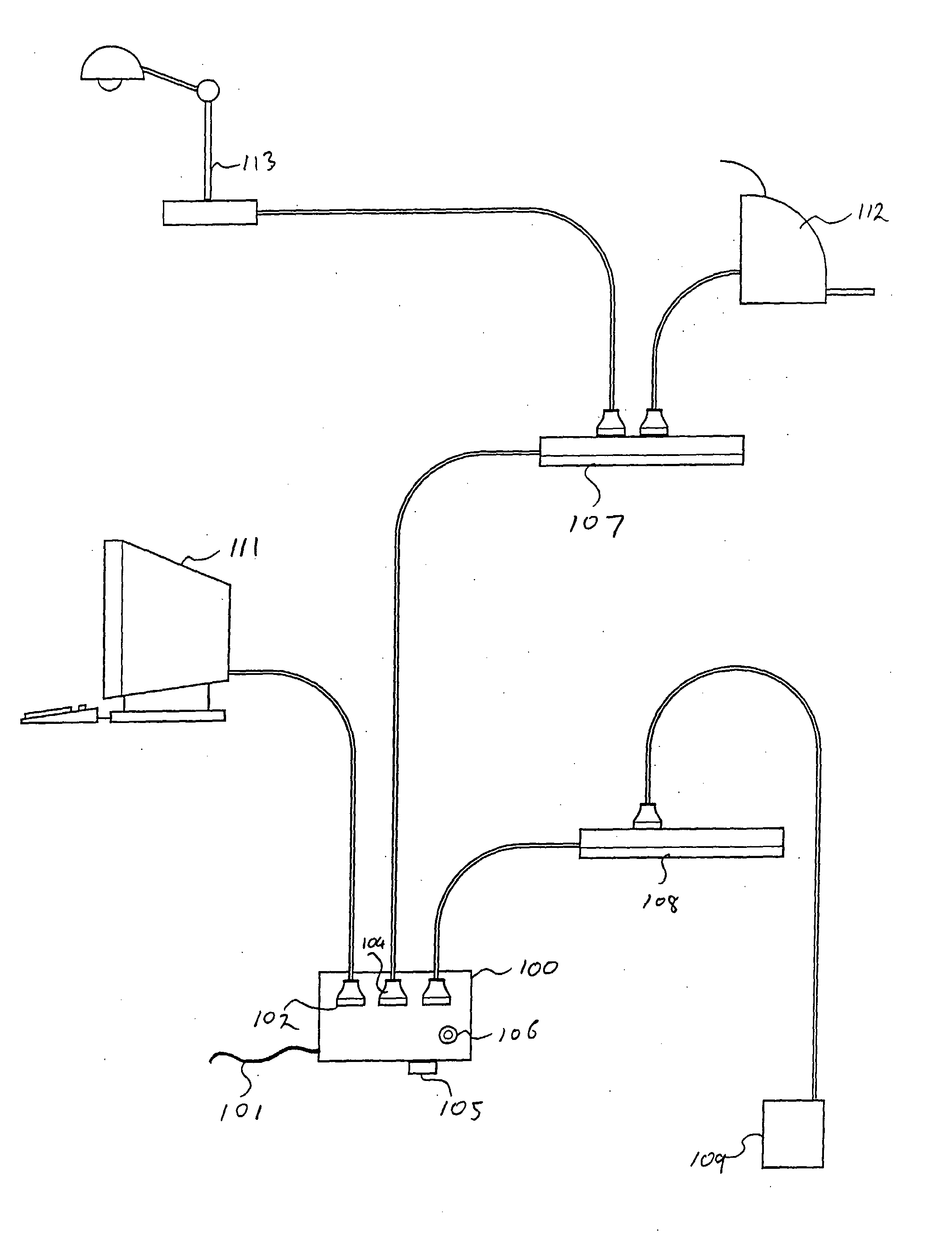
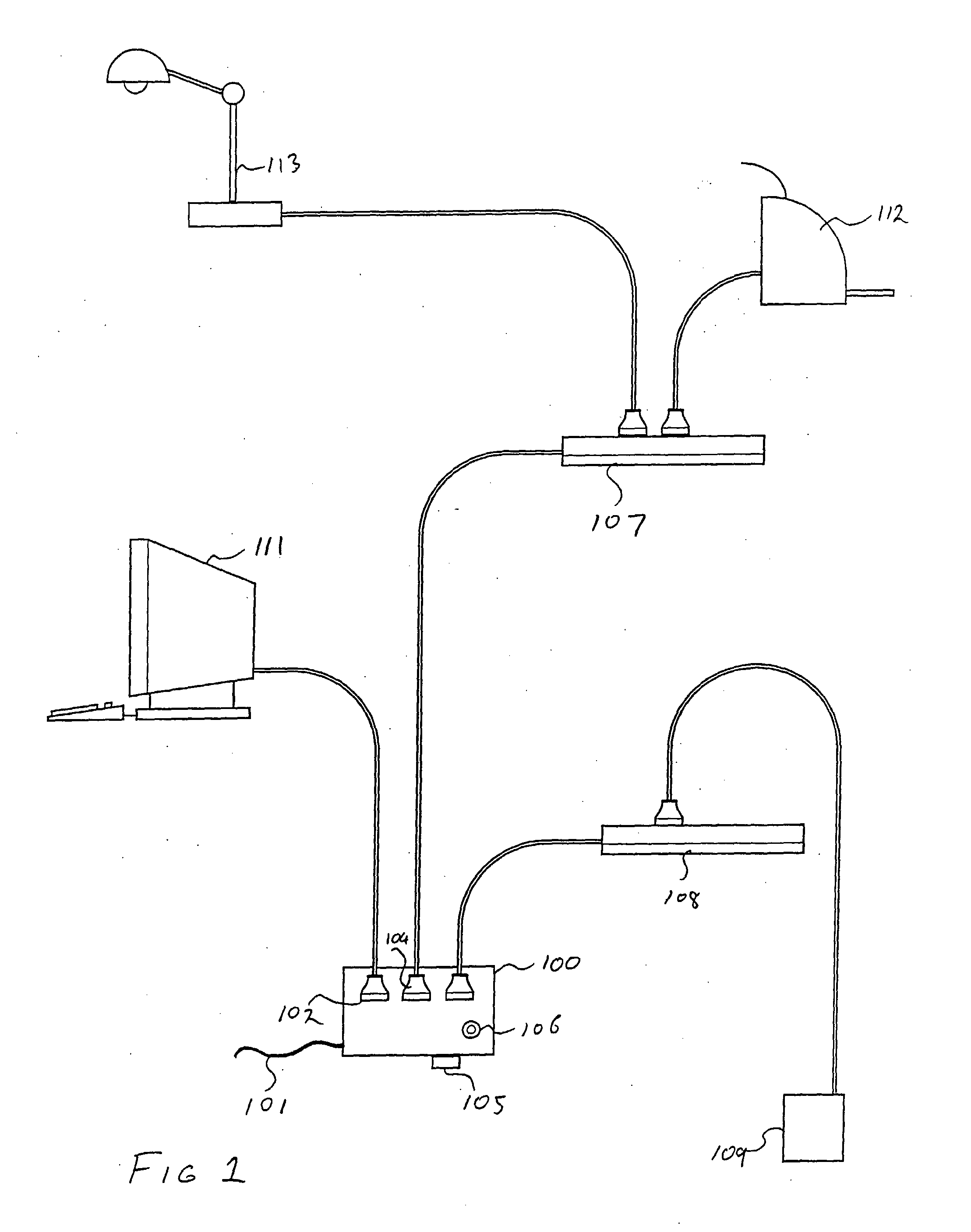
[0028]Turning now to FIG. 1 there is shown a perspective drawing of a power supply control device according to an embodiment of the invention. There is a box 100 containing the working circuitry of the device. There is a power cord 101 which is connected to a general-purpose electrical outlet. There is a power outlet 102 which is in permanent electrical connection with the mains power supply to the device. There is a power outlet 104 which is available to have connected to it such electrical loads as require power only when the main computer is in a full power mode. A power board or power strip 107 is connected to this outlet in order to allow multiple devices to be powered in this manner. Exemplary devices of this class, being a printer 112 and a desk lamp 113 are shown.

[0029]There is a further electrical outlet 103 which is available for the connection of loads which require power when the computer is in a fully on or a standby mode but which do not require power when the main com...


PUM


Abstract

A power supply control device for supplying power to a number of electrical devices from a single mains supply electrical outlet switch means adapted to connect an electrical supply from the supply electrical outlet to each of the controlled electrical outlets in response to the state of a master electrical device, a state sensor adapted to detect a functional state of the master electrical device, said sensor being adapted to distinguish at least three functional states of the master device. The master device may be personal computer with peripheral devices connected to the controlled outlets.

Description

TECHNICAL FIELD[0001]This invention relates to the control of the supply of electrical power to plug-in electrical equipment, in particular to the control of the supply of electrical power to groups of such electrical equipment where the power supply requirement of these groups is related to the operational status of a main piece of electrical equipment. More particularly it relates to the provision of electrical power to peripheral devices in a personal computer installation.BACKGROUND ART[0002]A desktop computer installation typically has associated with it a number of peripheral devices and other associated electrical devices, each of which is separately electrically powered. The peripheral devices can include such things as printers, scanners and modems or there may be associated devices such as a desk lamp or a room heater.[0003]These peripheral devices and associated electrical equipment are in general not used when the computer is not in use. However, because they are separat...

Claims


Application Information

Patent Timeline
Patent Type & Authority Applications(United States)
IPC IPC(8): G06F1/32H02J3/00G06F1/26G06F1/30
CPCG06F1/266G06F1/305Y02B60/1296G06F1/325G06F2200/261G06F1/3203Y02D10/00
Inventor GELONESE, GIUSEPPE ANTONIO
Owner EMBER TECH PTY LTD
Why Eureka
Try Eureka