Power supply control device

a power supply control and power supply technology, applied in the direction of power supply for data processing, instruments, originals for photomechanical treatment, etc., can solve the problems of large time consumption of computer operating systems, unsatisfactory, and inability to tolerate power removal from peripheral devices by computer systems. , to achieve the effect of simple and relatively time-consuming

Inactive Publication Date: 2012-10-30
EMBERTEC
View PDF12 Cites 9 Cited by
  • Summary
  • Abstract
  • Description
  • Claims
  • Application Information

AI Technical Summary

Benefits of technology

[0024]The modern desktop computer generally has a complex and relatively time consuming “power up sequence” which is the series of activities which the computer performs immediately upon being first switched on. This sequence may include activities to discover what peripheral devices are connected to the computer and to establish communication with such peripherals. One of the advantages of the standby mode is that it is not necessary for the computer to go through this power up sequence when it emerges from standby into fully powered mode.

Problems solved by technology

This is a time consuming process and indeed given the placement of the power switches on many such electrical devices, may be extremely inconvenient.
It is also the case that widely used computer operating systems require significant time to perform certain “housekeeping” tasks in between receiving command to shut down and actually shutting off the power or being in a position to have the power supply to the computer shut off without causing problems for the computer system.
During this time, the computer system also may not tolerate having power removed from peripheral devices.
This is not ideal for a number of reasons.
The first of these is that the devices continue to consume power which is both costly and a waste of resources.
This is particularly a problem since many modern devices use small plug-in transformers to provide the lower operating voltages which they require.
These plug-in transformers continue to consume power whilst they are connected to a mains supply even if the power switch on the device which they are supplying with power has been switched off.
Newer power supplies use solid state switching devices but still consume about 0.5 W.
Users may allow the device to spend extended periods in such a standby state, negating most of the advantages of the prior art devices.

Method used


Image

  • Power supply control device
  • Power supply control device
  • Power supply control device

Examples


Embodiment Construction

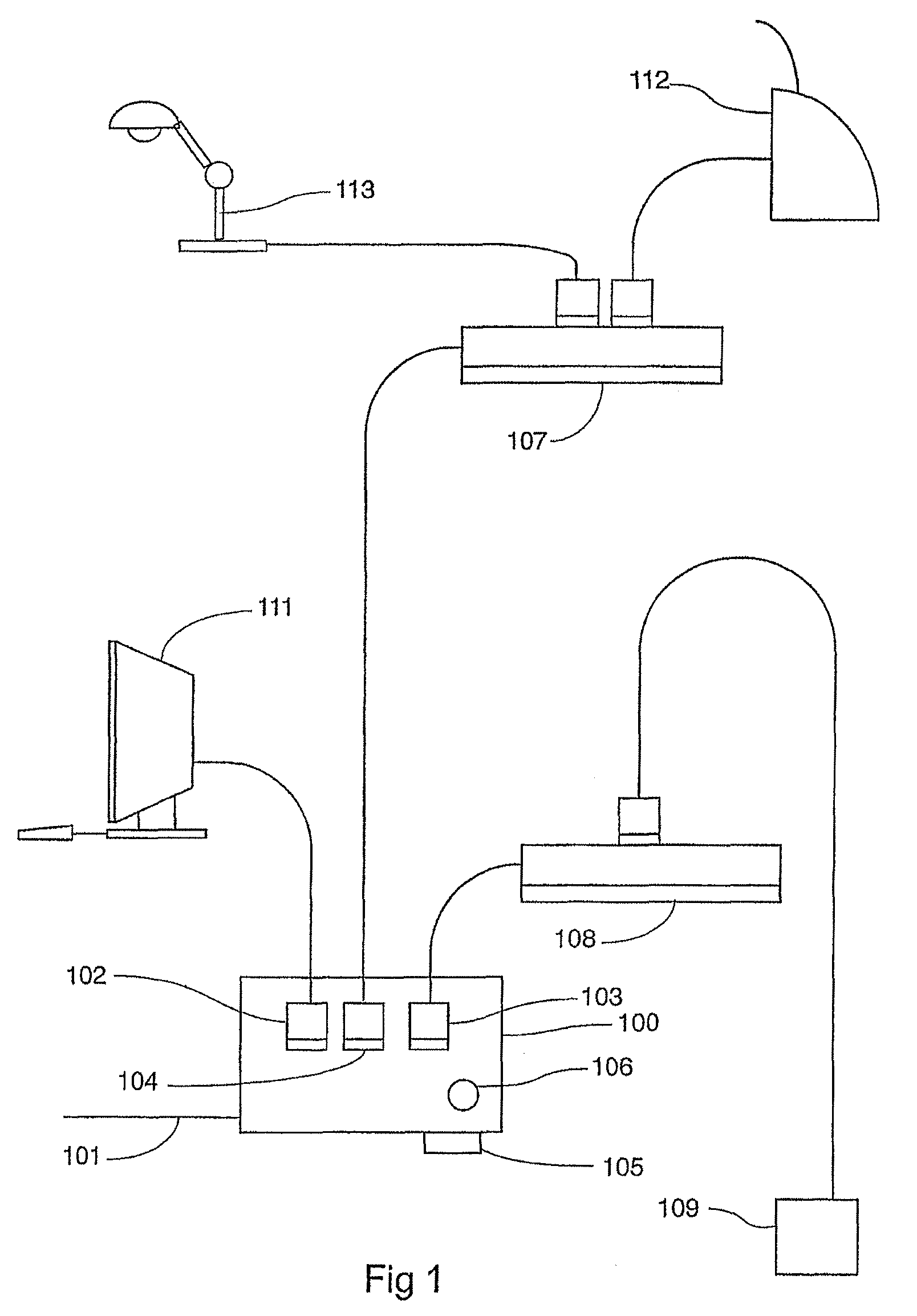
[0042]Turning now to FIG. 1 there is shown a perspective drawing of a power supply control device according to an embodiment of the invention. There is a box 100 containing the working circuitry of the device. There is a power cord 101 which is connected to a general-purpose electrical outlet. There is a power outlet 102 which is in permanent electrical connection with the mains power supply to the device. The main device to be powered, in this case a personal computer 111 is connected to this outlet. It is to be understood that the main device could be any other electrical device whose state determines the power requirements for other associated devices.

[0043]There is a power outlet 104 which is available to have connected to it such electrical loads as require power only when the main computer is in a full power mode. A power board or power strip 107 is connected to this outlet in order to allow multiple devices to be powered in this manner. Exemplary devices of this class, being ...


PUM

PropertyMeasurementUnit
timeaaaaaaaaaa
timeaaaaaaaaaa
timeaaaaaaaaaa

Abstract

The present invention discloses a power supply control device to which can be attached a number of electrical device(s), such as a computer or AV equipment. The power supply device is able to determine and monitor standby power usage levels of the device(s) so that when the control device detects that the connected electrical device(s) are not being used power supply is removed from the device(s).

Description

CROSS-REFERENCE TO RELATED APPLICATIONS[0001]This application is a bypass continuation in part, which claims priority to International Application No. PCT / AU2007 / 001824, filed Nov. 27, 2007, which claims priority to Australian Patent Application No. 2006906617, filed Nov. 27, 2006, and U.S. Non-provisional application Ser. No. 11 / 569,329, filed Aug. 13, 2007, which is a §371 National Stage entry of International Application No. PCT / AU2005 / 000707, filed May 18, 2005, which claims priority to Australian Patent Application No 2004902643, filed May 19, 2004, all of which are hereby incorporated by reference.TECHNICAL FIELD[0002]This invention relates to the control of the supply of electrical power to plug-in electrical equipment, in particular to the control of the supply of electrical power to groups of such electrical equipment where the power supply requirement of these groups is related to the operational status of a main piece of electrical equipment.BACKGROUND ART[0003]A desktop ...

Claims


Application Information

Patent Timeline
Patent Type & Authority Patents(United States)
IPC IPC(8): G03F1/00
CPCG06F1/26G06F1/3203
Inventor GELONESE, GIUSEPPE ANTONIO
Owner EMBERTEC
Why Eureka
Try Eureka