
Igniter safe and arm, igniter assembly and flare so equipped and method of providing a safety for an igniter assembly

a safety and igniter technology, applied in the field of new igniter assemblies, can solve the problems of insufficient remaining force imparted to the cable 230 by parachute deployment, inoperable igniter, and force upon the cabl

Active Publication Date: 2008-05-15
NORTHROP GRUMMAN SYST CORP
View PDF9 Cites 5 Cited by
  • Summary
  • Abstract
  • Description
  • Claims
  • Application Information

AI Technical Summary

Benefits of technology

[0016]Accordingly, in one embodiment, an igniter assembly overcoming the above-discussed problems includes a safety for preventing inadvertent ignition while allowing a combustible illuminant composition to be actuated by deployment of an associated parachute. An advantage provided by embodiments of this invention is an igniter assembly wherein the illumination composition inadvertent ignition sensitivity is substantially independent of circumferential clocking. Another advantage provided by embodiments of this invention is an igniter assembly that resists ignition of the illumination composition when subjected to an impact or impulse force, particularly when the force is applied in the zero degree orientation or in the direction of the slider's motion.

Problems solved by technology

However, the availability and widespread use of military flares has negated this advantage somewhat, since there is an increased likelihood of opposing military forces also possessing flares.
However, the remaining force imparted to the cable 230 by parachute deployment is not always sufficient to overcome additional frictional forces at the slider / raceway interface and the interface between the cocked striker arm 218 and the cam surface 225.
However, the igniter will be rendered inoperable if the static force required to release or break the bridge is sufficiently high enough to prevent against all inadvertent or unintentional firings, because the parachute, by way of the cable, will not provide reliable requisite force to break the bridge.
Also, as the force requirement increases for the bridge, the resultant resistance force upon the cable, along its path, junctions or bends to the parachute attachment, undesirably increases.
In this regard, the above mentioned patents due not provide against the unintended ignition of the illumination composition when the igniter assembly is subject to an impact or impulse force when dropped in a zero degree orientation, i.e. in the direction of the slider's motion.

Method used


Image

  • Igniter safe and arm, igniter assembly and flare so equipped and method of providing a safety for an igniter assembly
  • Igniter safe and arm, igniter assembly and flare so equipped and method of providing a safety for an igniter assembly
  • Igniter safe and arm, igniter assembly and flare so equipped and method of providing a safety for an igniter assembly

Examples


Embodiment Construction

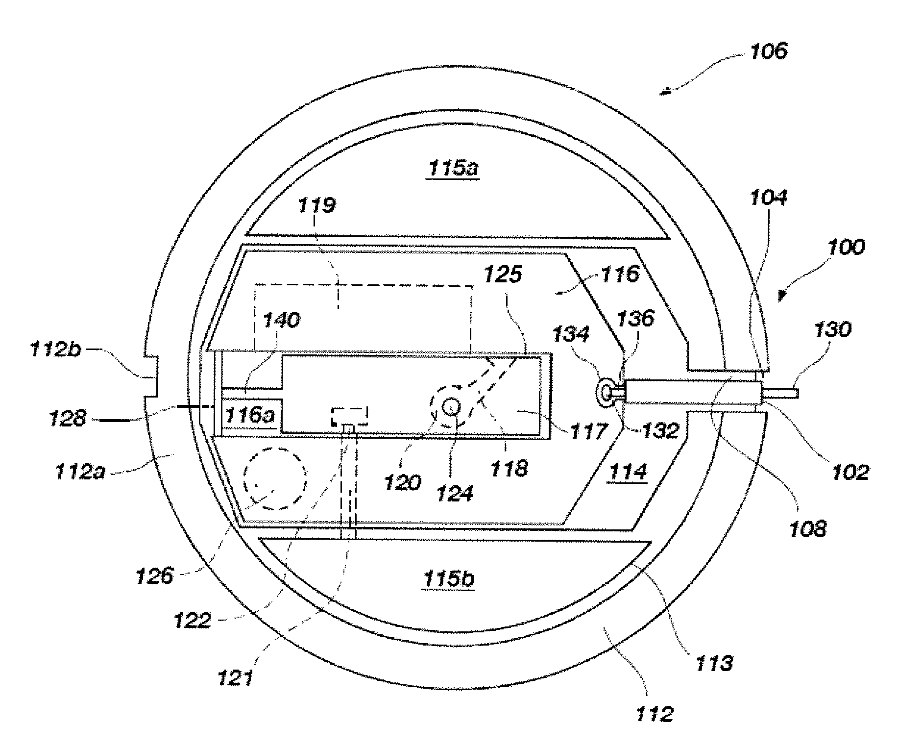
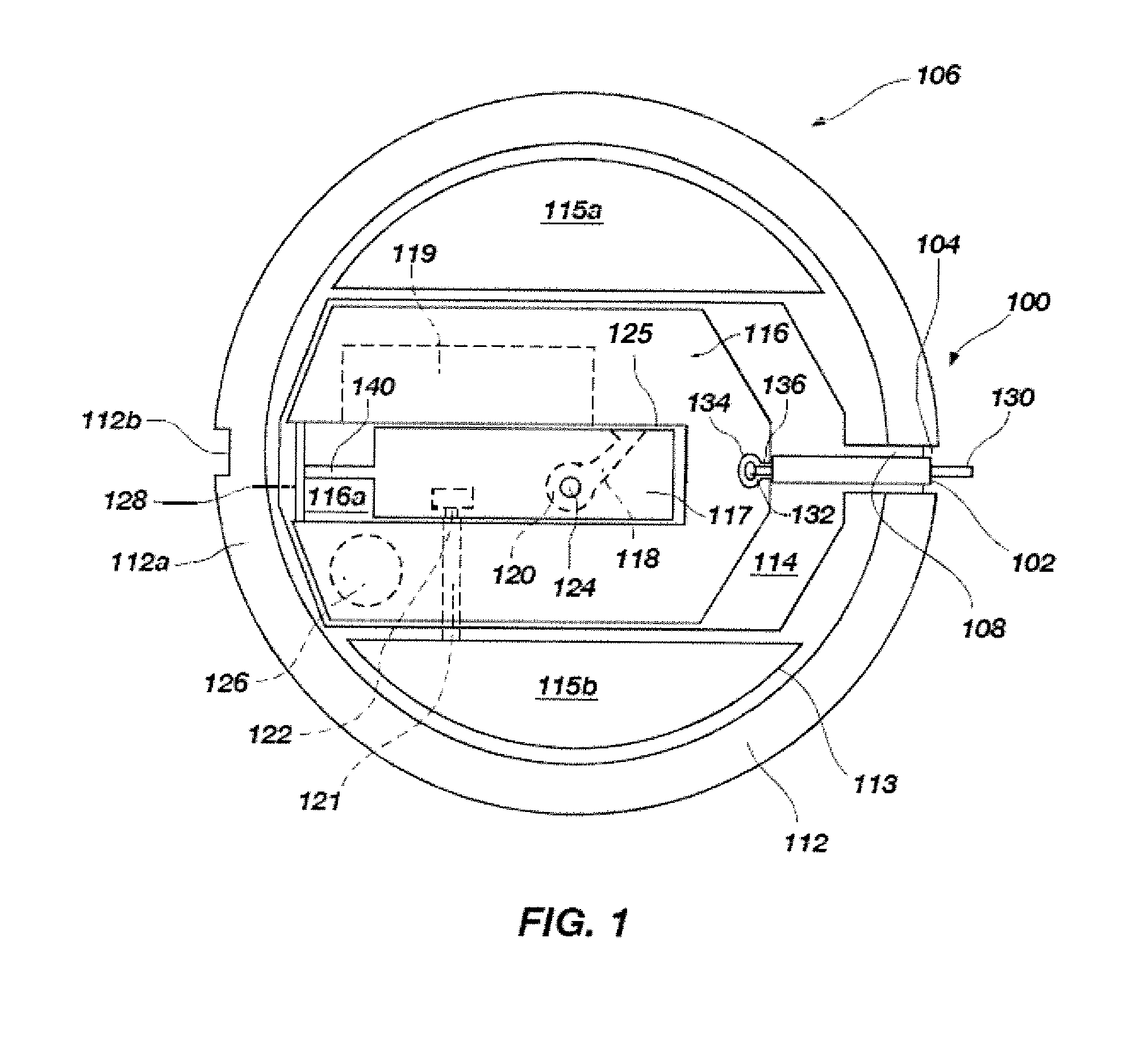
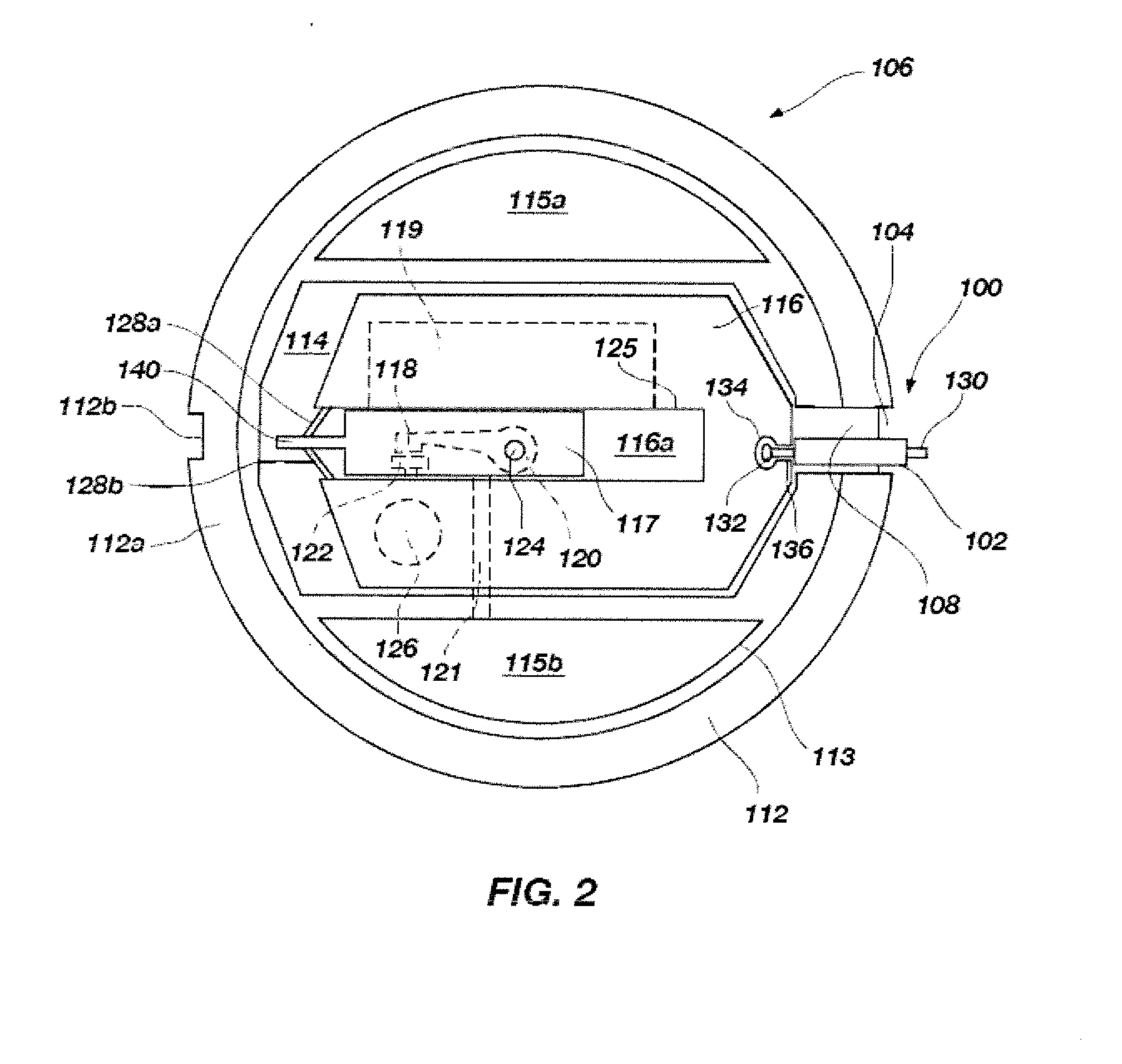
[0034]An example of a basic design of the illuminating flare with which the igniter of this invention is compatible is shown in FIG. 5 and discussed above. In the interest of brevity, and because the design of known illuminating flares is within the purview of one of ordinary skill in the art, the following discussion will be limited to embodiments of the novel igniter assembly having a safe configured in accordance with the present invention.

[0035]Referring to FIG. 1, the igniter assembly, or “igniter,”106 includes a housing 112 formed of a molded piece of LEXAN® or other polycarbonate and a safe 100. The housing 112 has longitudinally extending internal walls 113, which are receivable into an aluminum cap 150 (FIG. 4) of the casing so that peripheral portion 112a of the housing 112 abuts the periphery of the aluminum cap 150. Groove 112b may be used to assist in aligning the housing 112 and the aluminum cap 150 with the flare body. The internal walls 113 define a first hollow comp...


PUM


Abstract

A parachute flare igniter assembly includes a novel safety for arresting the motion of a slider when subjected to external forces, but allows slider motion when subjected to intended cable actuation forces. The igniter safety includes a housing, a slider, a cable and a sleeve. The slider, connected to the cable, is slidably received within the housing. The cable moves the slider by applying a cable force conventionally obtained by actuation of a parachute associated with the flare and connected to an end of the cable opposite an end connected to the slider. The sleeve is connected to the cable and is disposed between the housing and the slider, so that the sleeve will arrest the slider with respect to the housing when the cable force is not present. A flare and a method of providing a safety in an igniter assembly is also provided.

Description

[0001]This invention was made with Government support to Contract Numbers W52P1J-04-C-0002 and FA8213-04-C-0026. The Government has certain rights in this invention.FIELD OF THE INVENTION[0002]This invention, in various embodiments, relates to a novel igniter assembly for igniting combustible compositions in a highly reliable manner and, in particular, to an igniter assembly which includes a safety for preventing inadvertent ignition while allowing a combustible illuminant composition to be actuated by deployment of an associated parachute. Embodiments of the invention also relate to devices comprising the novel igniter assembly, such devices including, by way of example, illuminating flares.BACKGROUND OF THE INVENTION[0003]Among the various environments in which illuminating flares are used, perhaps the most common environment for the use of flares involves the illumination of military battle grounds. In such applications, the flares are launched above ground or water areas where e...

Claims


Application Information

Patent Timeline
IPC IPC(8): F42C15/00
CPCF41A19/08F42B4/28F42C15/184F42C15/295F42C15/23F42C15/28F42C15/20F42B12/36
Inventor RICHARDS, KEVIN W.DYE, KENDALLJONES, ROBERT G.
Owner NORTHROP GRUMMAN SYST CORP
Learn More