Wall-mountable smart dual load control device

a load control device and wall mount technology, applied in the direction of electric variable regulation, process and machine control, instruments, etc., can solve the problem that the load control device is not adapted to be coupled to the neutral connection

Inactive Publication Date: 2008-05-15
LUTRON TECH CO LLC
View PDF10 Cites 78 Cited by
  • Summary
  • Abstract
  • Description
  • Claims
  • Application Information

AI Technical Summary

Benefits of technology

[0008]According to the present invention, a wall-mountable load control device for individually controlling the power delivered from an AC power source to a first electrical load and a second electrical load is provided. The AC power source has a hot connection and a neutral connection, and the first and second electrical loads each have a first connection and a second connection. The second connections of both the first and second electrical loads are coupled to the neutral connection of the AC power source. The load control device comprises first and second controllably conductive devices, a control circuit, and a power supply. The first controllably conductive device has a control input and is adapted to be coupled between the hot connection of the AC power source and the first connection of the first electrical load for controlling the amount of power delivered to the first electrical load continuously from a maximum value to a minimum value. The second controllably conductive

Problems solved by technology

Further, the load control device is not adapted to be c

Method used


Image

  • Wall-mountable smart dual load control device
  • Wall-mountable smart dual load control device
  • Wall-mountable smart dual load control device

Examples


Embodiment Construction

[0017]The foregoing summary, as well as the following detailed description of the preferred embodiments, is better understood when read in conjunction with the appended drawings. For the purposes of illustrating the invention, there is shown in the drawings an embodiment that is presently preferred, in which like numerals represent similar parts throughout the several views of the drawings, it being understood, however, that the invention is not limited to the specific methods and instrumentalities disclosed.

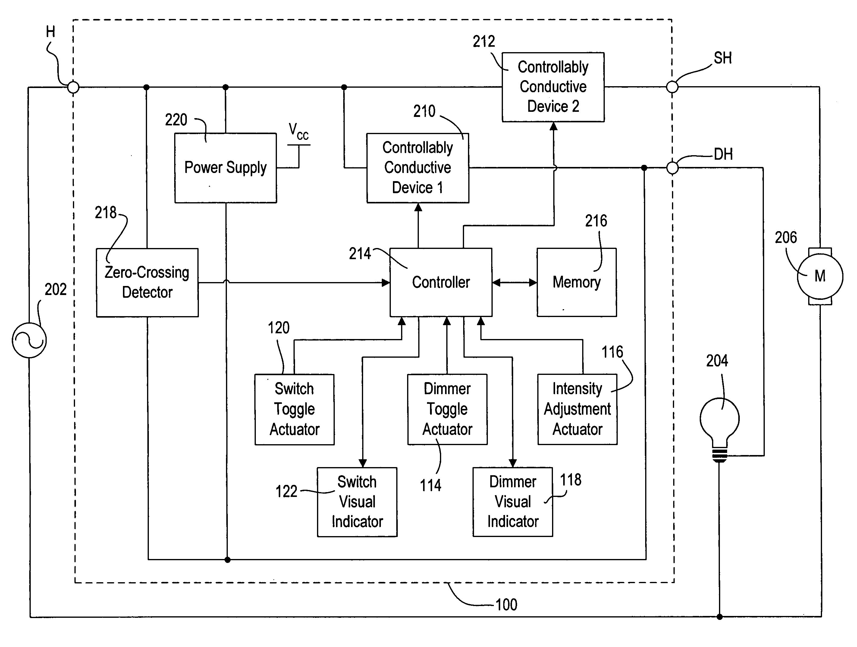
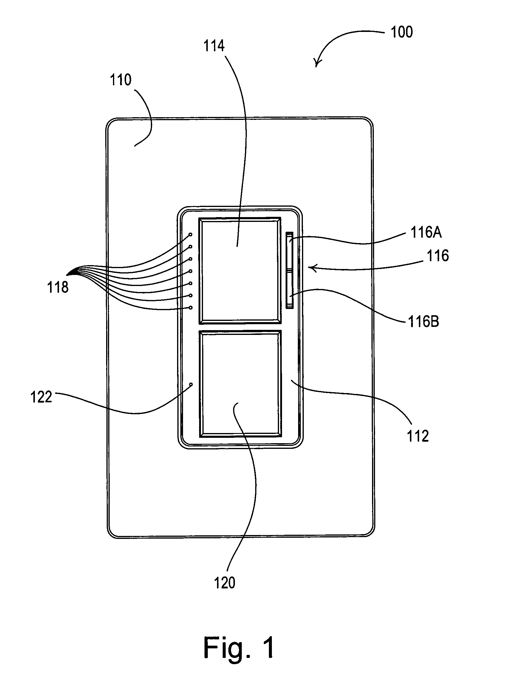
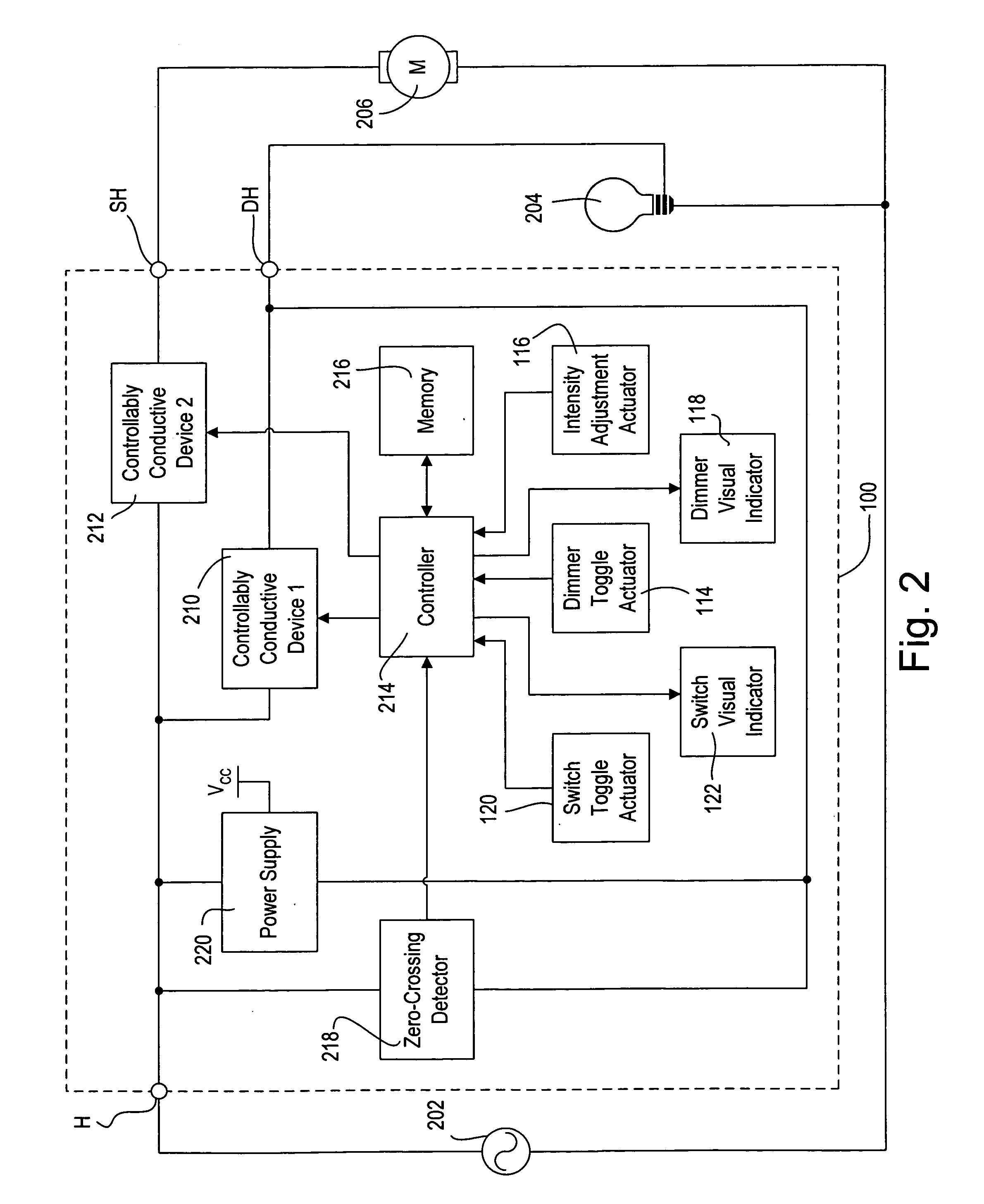
[0018]FIG. 1 is a front view of a smart dual switch and dimmer 100 (i.e., a dual “switch / dimmer”) operable to independently control two separate electrical loads according to the present invention. FIG. 2 is a simplified block diagram of the dual switch / dimmer 100. The dual switch / dimmer 100 is operable to control the amount of power delivered from an alternating-current (AC) power source 202 to the first electrical load (e.g., a lighting load 204 shown in FIG. 2) using a phase-...


PUM


Abstract

A smart dual load control device is operable to control the amount of power delivered from an AC power source to a first electrical load and to switch the power delivered from the AC power source to a second electrical load between an on state and an off state, while providing an advanced set of control features and feedback options to an end user. A control circuit is coupled to first and second controllably conductive devices for controlling the amount of power delivered to the first and second electrical loads, respectively. A power supply generates a DC voltage to power the control circuit and is coupled in parallel electrical connection with the first controllably conductive device such that the power supply is operable to draw current through the first electrical load. The second controllably conductive device is operable to provide substantially zero current through the second electrical load when the second electrical load is in the off state.

Description

BACKGROUND OF THE INVENTION[0001]1. Field of the Invention[0002]The present invention relates to dual load control devices for independently controlling the amount of power delivered to two electrical loads from a source of alternating-current (AC) power, and more particularly, to a smart load control device for dimming a first electrical load and switching a second electrical load.[0003]2. Description of the Related Art[0004]Often, two electrical loads are controlled from a wall-mountable load control device mounted in a single-gang electrical wallbox. For example, a lighting load and a motor load, such as an exhaust fan, are often controlled from a single wall-mountable load control device in a bathroom. A common single-gang load control device for control of two electrical loads is a dual switch, which simply comprises a first mechanical switch coupled in series between an AC power source and the first electrical load, and a second mechanical switch coupled in series between the ...

Claims


Application Information

Patent Timeline
IPC IPC(8): H05B41/38
CPCH05B37/0281Y02B20/48Y02B20/42H05B39/044H05B47/16H05B47/185Y02B20/00Y02B20/40
Inventor DOBBINS, AARONMCCARTER, KYLE A.
Owner LUTRON TECH CO LLC
Why Eureka
Try Eureka