
Shoe Sole with Shock Absorbing Capability

Inactive Publication Date: 2008-05-22
SHYANG SHIN BAO IND
View PDF18 Cites 43 Cited by
  • Summary
  • Abstract
  • Description
  • Claims
  • Application Information

AI Technical Summary

Problems solved by technology

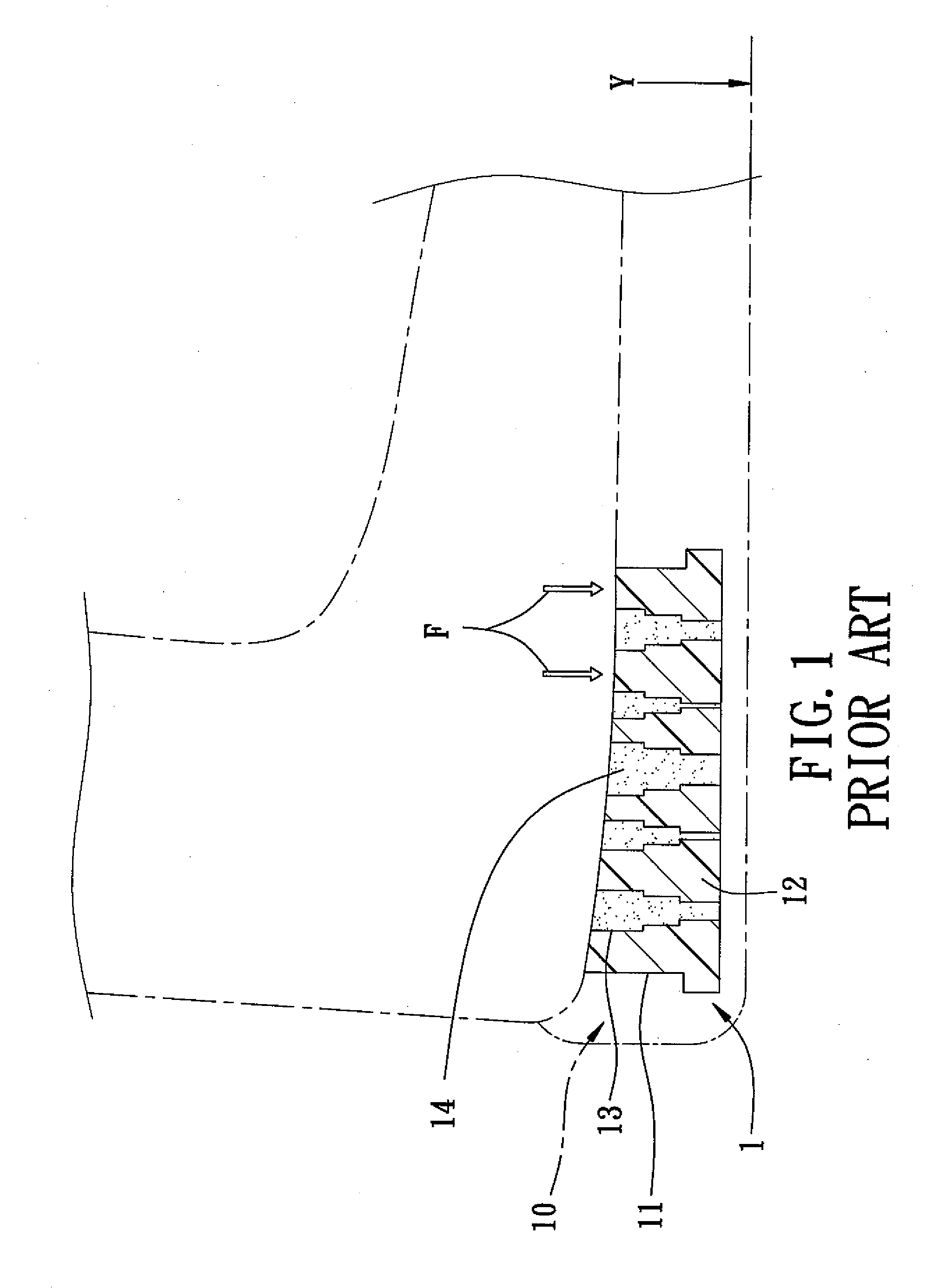
However, since the structure thus formed for the elastic body 12 has a relatively poor compressibility in a compression direction (Y) toward the ground, the shock absorbing effect provided by the conventional shoe sole 1 is relatively poor when a downward force (F) is applied to the shoe sole 1.

Method used


Image

  • Shoe Sole with Shock Absorbing Capability
  • Shoe Sole with Shock Absorbing Capability
  • Shoe Sole with Shock Absorbing Capability

Examples


Embodiment Construction

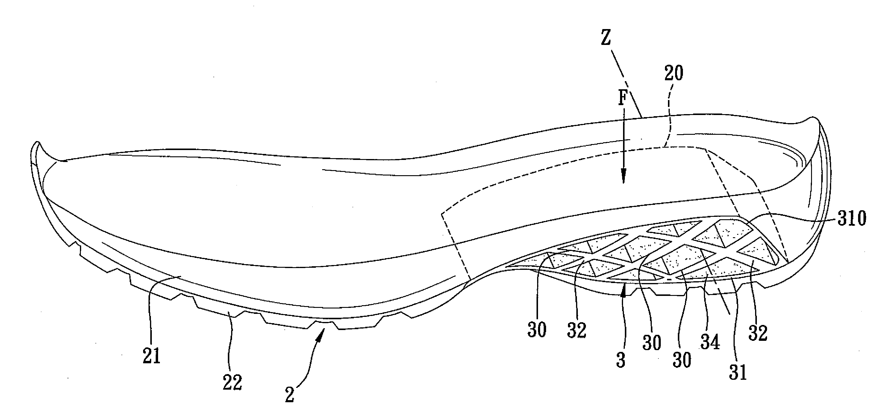
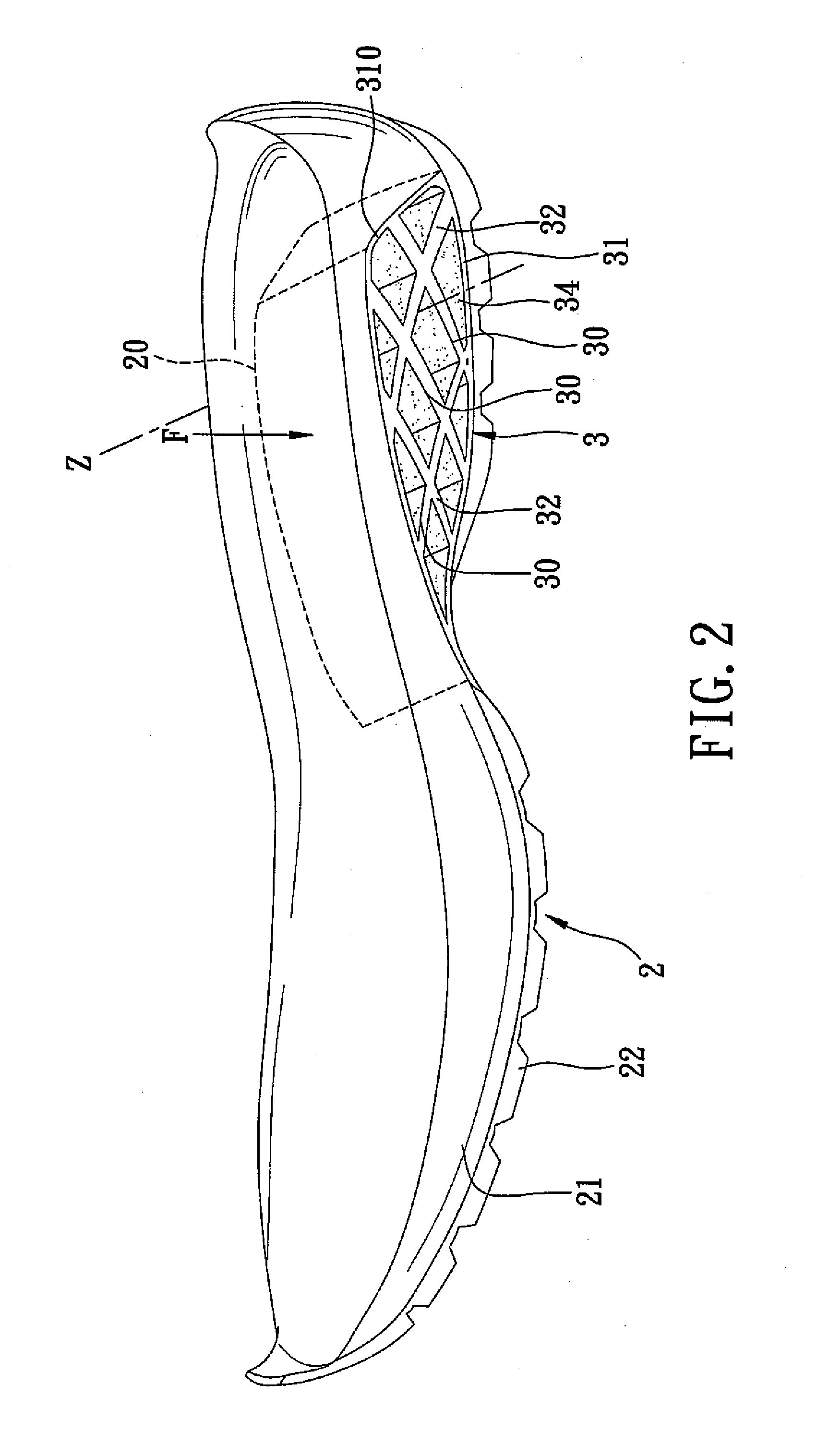
[0018]FIGS. 2 to 4 illustrate the first preferred embodiment of a shoe sole of a footwear article according to this invention.

[0019]The shoe sole includes: a sole unit 2 defining at least one recess 20; at least one elastic body 3 received in the recess 20 and having a cellular structure that defines at least two levels of cells 30, the two levels of the cells 30 being disposed one above the other, each of the cells 30 defining a cell space therein; and a filler material 34 that fills the cell space of each of the cells 30.

[0020]In this embodiment, the sole unit 2 includes an outsole 21 that defines the recess 20 disposed at a heel portion of the shoe sole, and a tread member 22 attached to the outsole 21 and covering a bottom side of the recess 20. The cellular structure of the elastic body 3 has a surrounding wall 31 that defines an inner space 310 and that is disposed between and that is attached to the outsole 21 and the tread member 22, and a plurality of interconnected webs 32...


PUM


Abstract

A shoe sole includes: a sole unit defining at least one recess; at least one elastic body received in the recess and having a cellular structure that defines at least two levels of cells, the two levels of the cells being disposed one above the other, each of the cells defining a cell space therein; and a filler material that fills the cell space of each of the cells.

Description

BACKGROUND OF THE INVENTION[0001]1. Field of the Invention[0002]This invention relates to a shoe sole, more particularly to a shoe sole including an elastic body having a cellular structure that defines a plurality of horizontally extending cells.[0003]2. Description of the Related Art[0004]FIG. 1 illustrates a conventional shoe sole 1 attached to an upper of a footwear article. The shoe sole 1 includes an outsole 10 formed with a recess 11, and an elastic body 12 received in the recess 11. The elastic body 12 is formed with a plurality of vertically extending through-holes 13, each of which is filled with a filler 14 so as to provide a shock absorbing effect. However, since the structure thus formed for the elastic body 12 has a relatively poor compressibility in a compression direction (Y) toward the ground, the shock absorbing effect provided by the conventional shoe sole 1 is relatively poor when a downward force (F) is applied to the shoe sole 1.SUMMARY OF THE INVENTION[0005]Th...

Claims


Application Information

Patent Timeline
IPC IPC(8): A43B13/42A43B13/00A43B13/18
CPCA43B13/181A43B13/189A43B13/187
Inventor HSIEH, JOEY
Owner SHYANG SHIN BAO IND
Learn More