Environmental seal for fluid delivery device

a technology for fluid delivery and environmental sealing, which is applied in the direction of other medical devices, catheters, valves, etc., can solve the problems that the known methods for assembling environmental seals are not well suited for miniaturization

Active Publication Date: 2008-05-22
INSULET CORP
View PDF22 Cites 55 Cited by
  • Summary
  • Abstract
  • Description
  • Claims
  • Application Information

AI Technical Summary

Problems solved by technology

Unfortunately, known methods for assembling environmental seals are not well suited for miniaturization with high quality and reliability and low cost.

Method used


Image

  • Environmental seal for fluid delivery device
  • Environmental seal for fluid delivery device
  • Environmental seal for fluid delivery device

Examples


Embodiment Construction

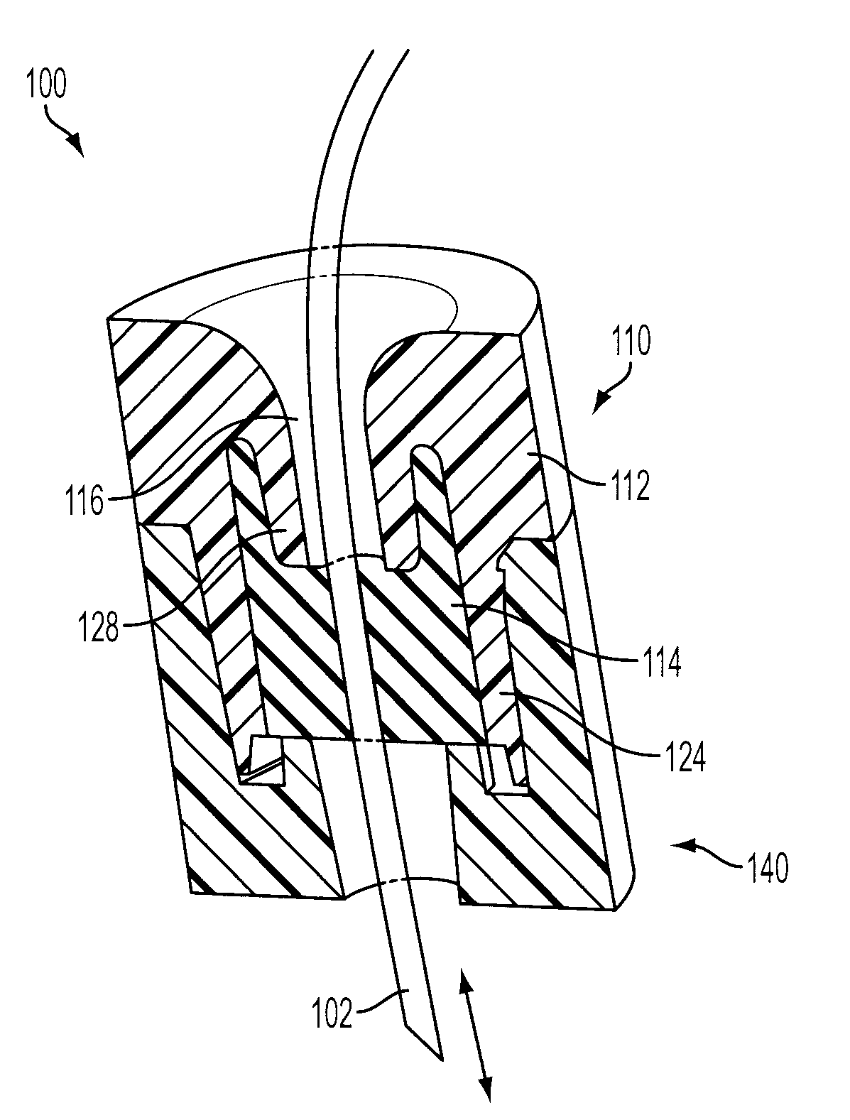
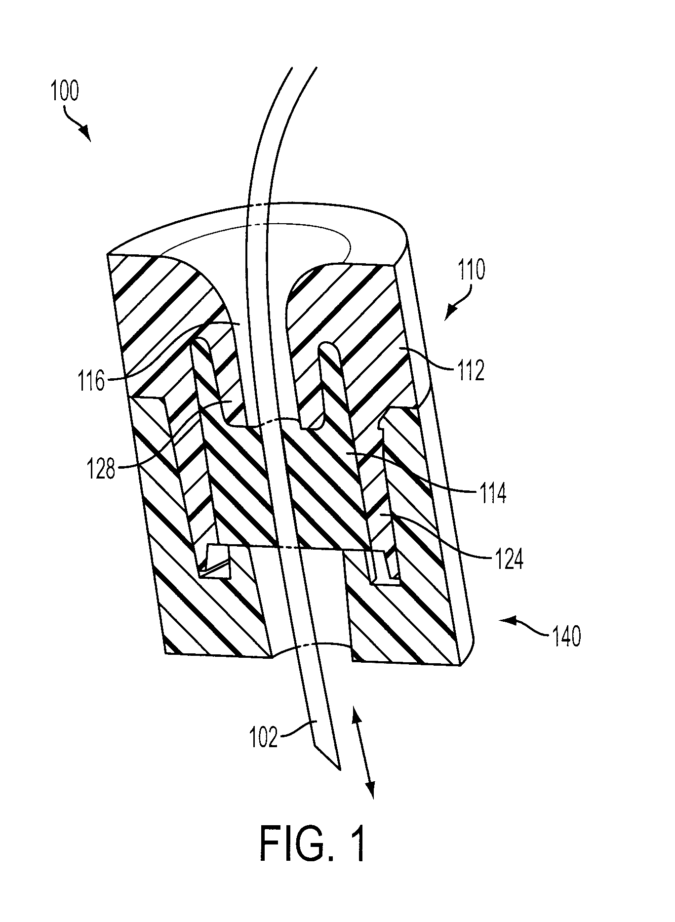
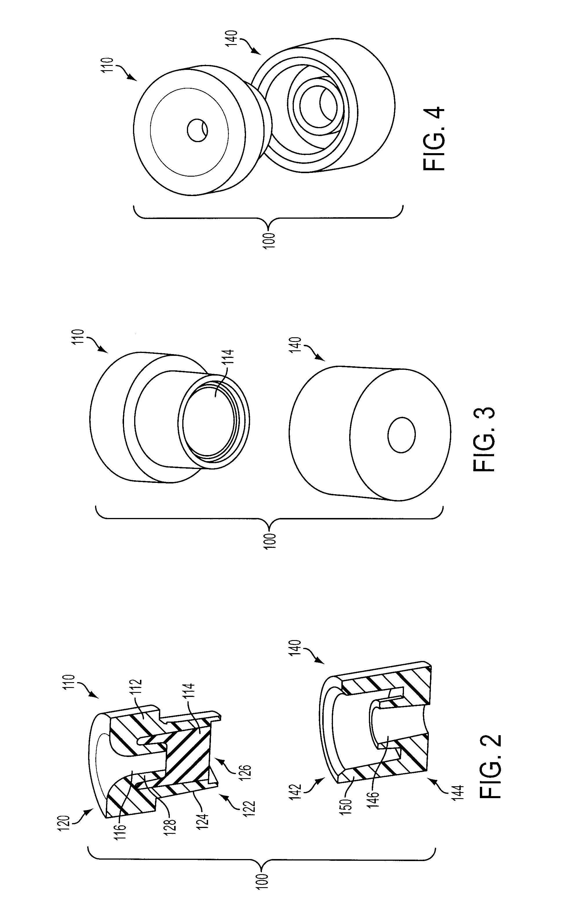
[0010]Referring to FIGS. 1-4, the present invention is directed to an environmental seal 100 for a fluid delivery device. The environmental seal 100 may be configured to receive a cannula 102 or other similar structure providing a fluid pathway. The environmental seal 100 comprises a cap 110 comprising a carrier 112 and a plug 114. The carrier 112 is preferably a relatively high durometer molded plastic component having a solid form and a channel 116 through the solid. The carrier portion 112 of the cap 110 may have a cylindrical shape with the channel 116 passing from the proximal end 120 to the distal end 122. The distal end 122 of the carrier 112 may comprise a sleeve portion 124 surrounding the plug 114. The sleeve portion 124 preferably defines a widened area of the channel 116 forming a cavity 126 at the distal end 122 of the carrier 112. The carrier 112 may also comprise a circumferential flange 128 defining the narrow portion of the channel 116 and extending into the cavity ...


PUM


Abstract

An environmental seal for a fluid delivery device may include a 2-shot molded cap including a carrier and a low durometer silicone plug. The seal also may include a cap receptacle that applies compressive force to the plug displacing the plug material and forming a seal between the cap, the plug and the cap receptacle. A cannula may be slidably received in the plug and may move freely through the plug without compromising the seal.

Description

CROSS-REFERENCE TO RELATED APPLICATION[0001]The present application claims the benefit of U.S. Provisional Patent Application Ser. No. 60 / 829,984 filed Oct. 18, 2006, which is fully incorporated herein by reference.TECHNICAL FIELD[0002]The present invention relates to fluid delivery devices and more particularly, to an environmental seal in the fluid pathway of a fluid delivery device.BACKGROUND INFORMATION[0003]Among fluid delivery devices, especially for medical applications, there is often a need to provide an environmental seal around a fluid pathway as it passes from one environment to another and / or where one cannula portion is joined to another. Such an environmental seal might, for example, serve to exclude water from the interior of a device, such as an infusion pump. Such an environmental seal might also serve to exclude the passage of air from one environment to another to limit the transmission of microorganisms from one environment to another, or to maintain the integri...

Claims


Application Information

Patent Timeline
Patent Type & Authority Applications(United States)
IPC IPC(8): F16L5/02
CPCA61M39/04A61M39/06F16L5/10A61M2039/066A61M39/20
Inventor ANDERSON, MARCGARIBOTTO, JOHNDILANNI, STEVEN
Owner INSULET CORP
Why Eureka
Try Eureka