
Method and System for Detecting, and Controlling Power for, an Auxiliary Microphone

a technology of auxiliary microphones and power supply, applied in the direction of stereophonic circuit arrangements, transducer details, electrical transducers, etc., can solve the problem of excessive power drain and may still be presen

Inactive Publication Date: 2008-06-05
AVAGO TECH INT SALES PTE LTD
View PDF2 Cites 38 Cited by
  • Summary
  • Abstract
  • Description
  • Claims
  • Application Information

AI Technical Summary

Problems solved by technology

This may be problematic, especially for a mobile device that may depend on battery power.
However, if a user forgets to disable a functionality, then the original problem of excessive power drain may still be present.

Method used


Image

  • Method and System for Detecting, and Controlling Power for, an Auxiliary Microphone
  • Method and System for Detecting, and Controlling Power for, an Auxiliary Microphone
  • Method and System for Detecting, and Controlling Power for, an Auxiliary Microphone

Examples


Embodiment Construction

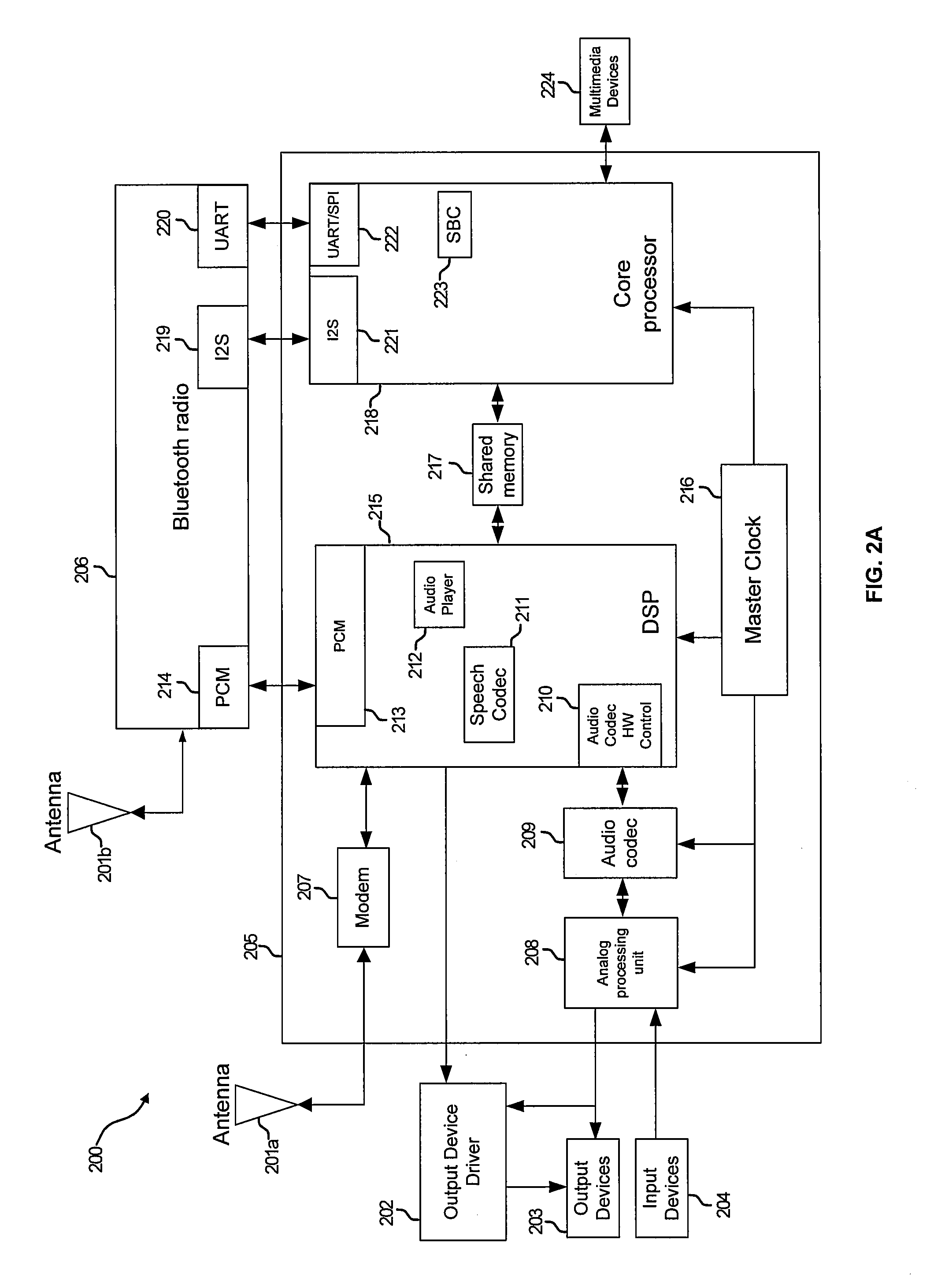
[0028]Certain embodiments of the invention may be found in a method and system for detecting, and controlling power for, an auxiliary microphone. Aspects of the method may comprise a detection block intermittently enabling a bias circuit block to provide a bias signal to determine if an auxiliary microphone may be communicatively coupled to a mobile device. The detection block may process 1-bit digital samples received from the bias circuit block to determine whether the auxiliary microphone may be plugged in. The detection block may also process the 1-bit digital samples to determine if a button associated with the auxiliary microphone may have been pushed or otherwise activated.

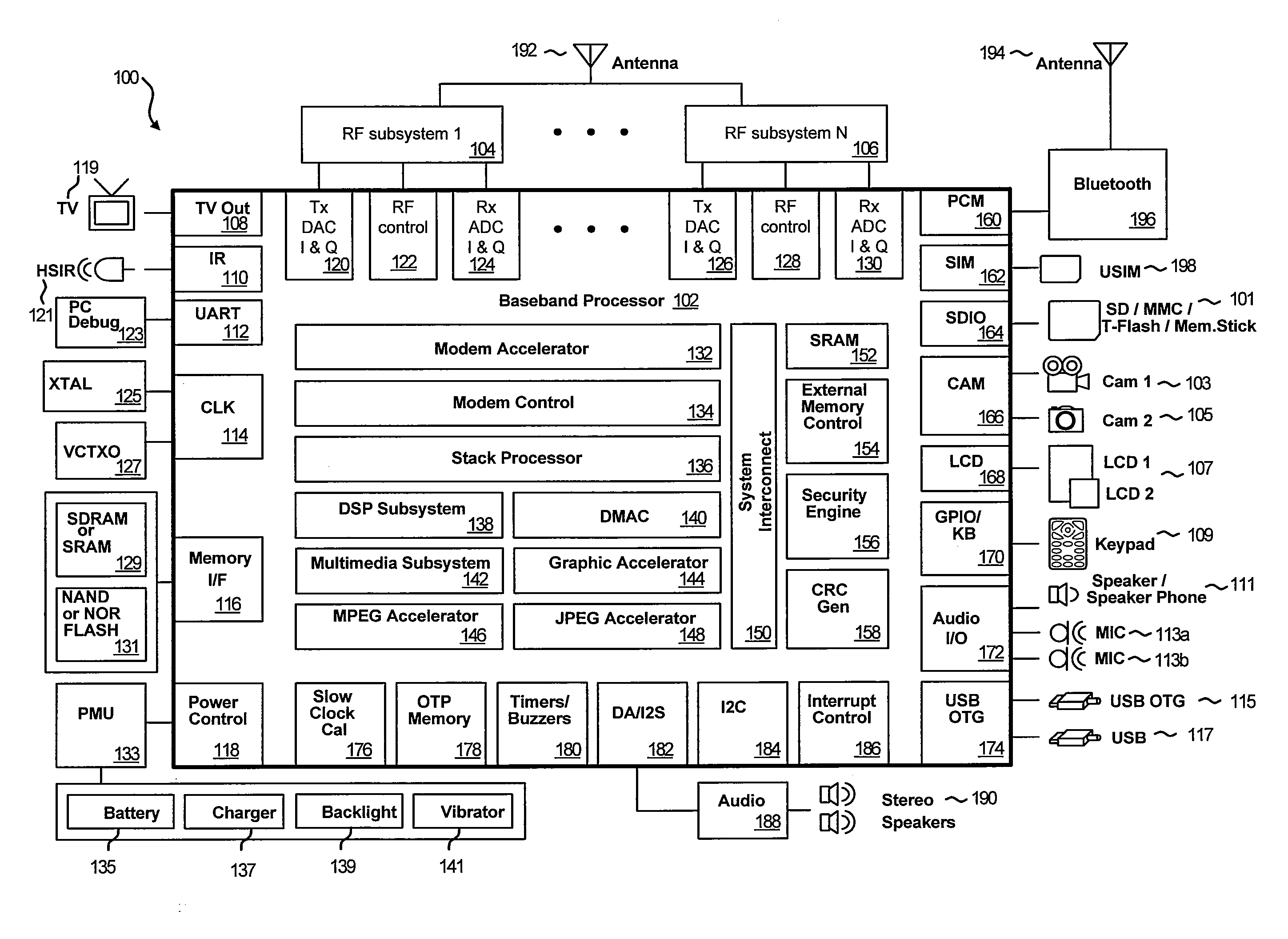
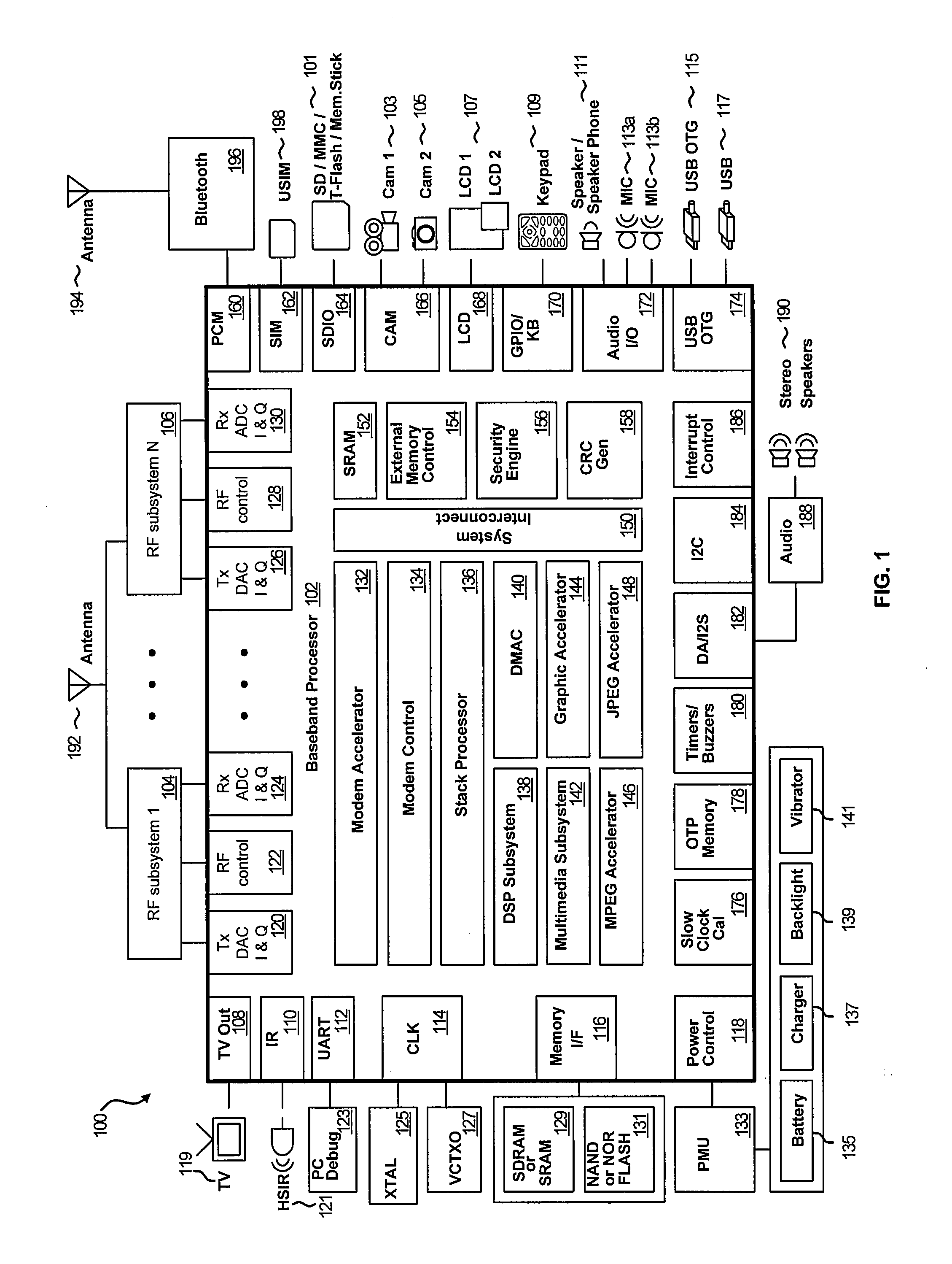
[0029]FIG. 1 is a block diagram that illustrates an exemplary multimedia baseband processor that enables handling of a plurality of wireless protocols, which may be utilized in connection with an embodiment of the invention. Referring to FIG. 1, there is shown a wireless system 100 that may correspond to a ...


PUM


Abstract

Methods and systems for detecting, and controlling power for, an auxiliary microphone are disclosed. Aspects of one method may include a detection block intermittently enabling a bias circuit block to provide a bias signal to determine if an auxiliary microphone may be communicatively coupled to a mobile device. The detection block may process 1-bit digital samples received from the bias circuit bock to determine whether the auxiliary microphone may be communicatively coupled. The detection block may also process the 1-bit digital samples to determine if a button associated with the auxiliary microphone may have been pushed or activated.

Description

CROSS-REFERENCE TO RELATED APPLICATIONS / INCORPORATION BY REFERENCE[0001]This application makes reference to:[0002]U.S. patent application Ser. No. ______ (Attorney Docket Number 18014US01) filed on even date herewith;[0003]U.S. patent application Ser. No. ______ (Attorney Docket Number 18015US01) filed on even date herewith; and[0004]U.S. patent application Ser. No. ______ (Attorney Docket Number 18016US01) filed on even date herewith;[0005]U.S. patent application Ser. No. ______ (Attorney Docket Number 18017US01) filed on even date herewith; and[0006]U.S. patent application Ser. No. ______ (Attorney Docket Number 18018US01) filed on even date herewith.[0007]Each of the above stated applications is hereby incorporated herein by reference in its entirety.FEDERALLY SPONSORED RESEARCH OR DEVELOPMENT[0008][Not Applicable]MICROFICHE / COPYRIGHT REFERENCE[0009][Not Applicable]FIELD OF THE INVENTION[0010]Certain embodiments of the invention relate to processing signals at a wireless mobile t...

Claims


Application Information

Patent Timeline
Patent Type & Authority Applications(United States)
IPC IPC(8): H04R3/00
CPCH04R5/04H04R2499/11H04R2420/07H04R2420/01
Inventor KONG, HONGWEISOLLENBERGER, NELSONCHANG, LI FUNGTONG, ANDYBROOKS, TODD L.HAYEK, CLAUDE
Owner AVAGO TECH INT SALES PTE LTD
Learn More