
Charging device for hearing aid

a charging device and hearing aid technology, applied in electrical appliances, transportation and packaging, electric vehicles, etc., can solve the problems of insufficient space, difficulty in removing the battery from the hearing aid, and difficulty in charging the battery by induction

Inactive Publication Date: 2008-06-12
SIEMENS AUDIOLOGISCHE TECHN
View PDF6 Cites 65 Cited by
  • Summary
  • Abstract
  • Description
  • Claims
  • Application Information

AI Technical Summary

Benefits of technology

[0017]A suitable opening in the housing of the hearing aid can be provided for the contact element. According to a preferred aspect of this invention, an outer surface of the contact element closes essentially flush with the surface of the housing of the hearing aid in the first position (i.e. in the operating or at-rest position). This is aesthetically attractive and pleasing to the touch and has the advantage that the ingress of cerumen to the inside of the hearing aid at this point is prevented.
[0018]According to an alternative aspect, the contact element in the second position can be lowered into a recess in the hearing aid housing. This is advantageous with a corresponding charging device that has a pin-type charging contact which can then engage in the recess of the hearing aid housing and contact the contact element.
[0020]In the second position (i.e. during a charging state), the contact element of the hearing aid can project out from the hearing aid housing. The contact element can, for example, be designed as a pin that can be moveably mounted on the hearing aid so that in the second position it can be pushed through an opening in the hearing aid housing and project out of the housing. In this state, the contact element can then be contacted without difficulty by the charging contact of the charging device.

Problems solved by technology

This presents the problem that the battery has to be recharged at periodic intervals, which usually takes place in a charging device.
Because hearing aids, especially in-the-ear (ITE) devices are extremely small, it is difficult to remove the battery from the hearing aid.
A battery that can be charged by induction is expensive to produce and requires additional space, which is always very restricted in a hearing aid.
Charging by induction also requires a more expensive charging device and causes a high energy consumption.
A charging device of this kind is expensive because the charging contacts are integrated into a customized component.

Method used


Image

  • Charging device for hearing aid
  • Charging device for hearing aid
  • Charging device for hearing aid

Examples


Embodiment Construction

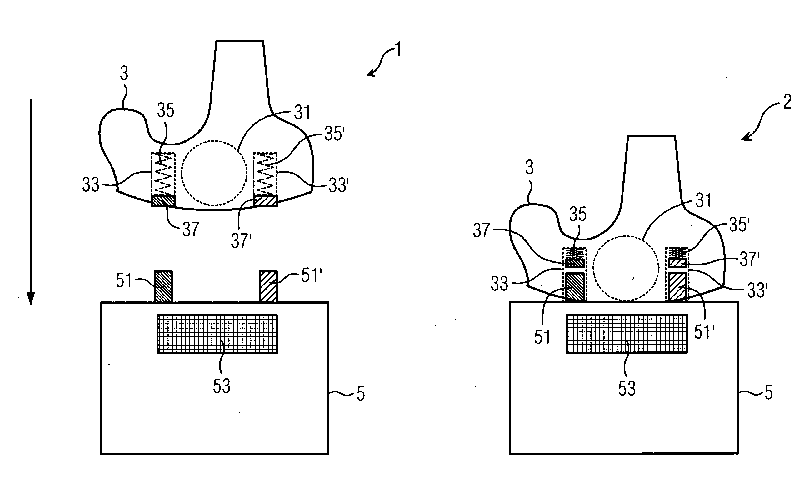
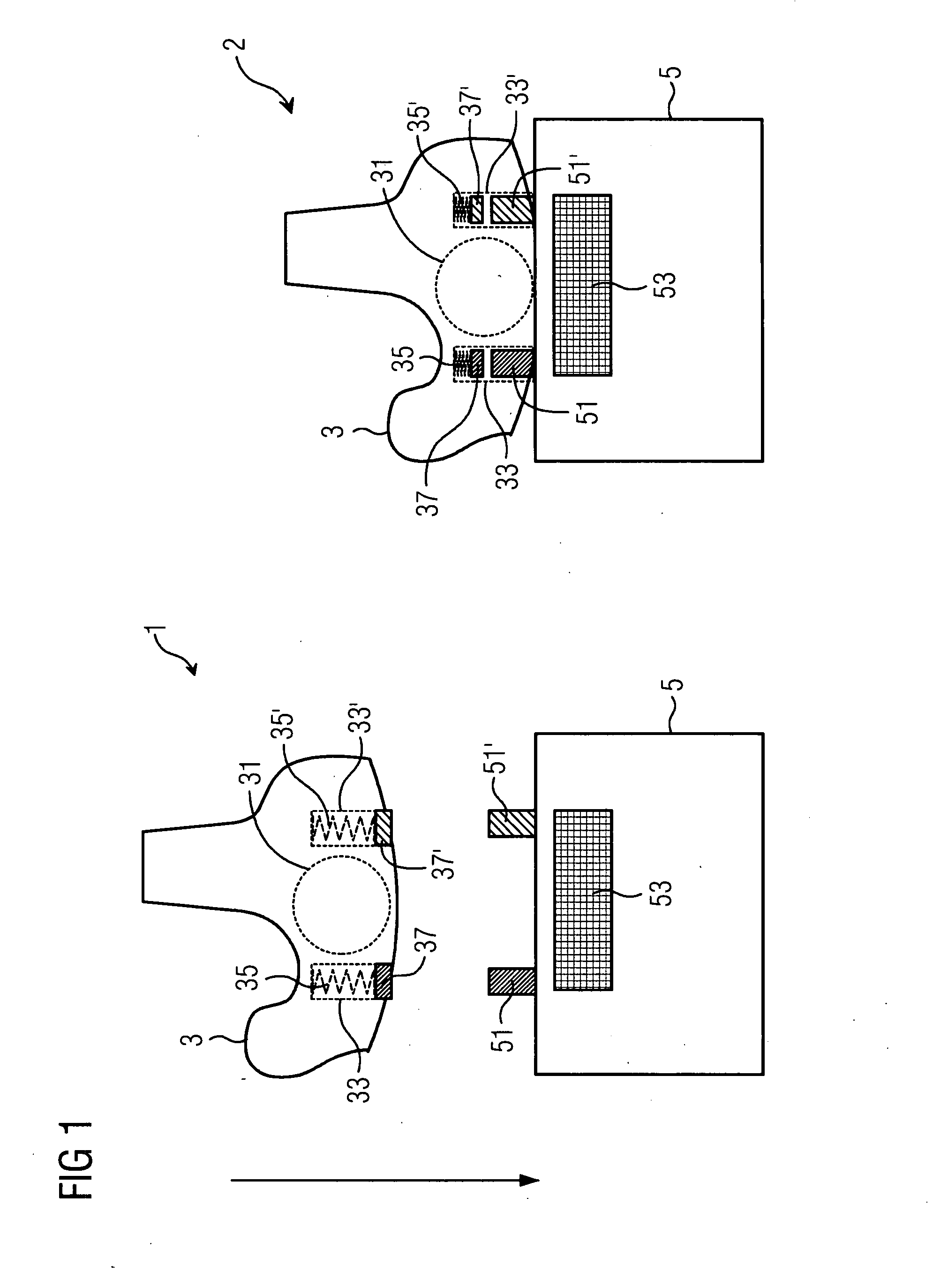
[0029]FIG. 1 shows a hearing aid 3 and associated charging device 5 in a first position 1 and a second position 2. The hearing aid 3 is an in-the-ear (ITE) hearing aid and it contains a battery 31. Two openings with guides 33 and 33′ are provided in the housing of said hearing aid 3. Reset elements 35 and 35′ in the form of coil springs, on the ends of which are contact elements 37 and 37′, are located in the guides. The contact elements 37, 37′ are moveably fitted in the guides 33, 33′ and in the first position (i.e. in an operating or at-rest state of the hearing aid without interaction with the charging device) are in a position in which the outer surface of the contact elements 37, 37′ is essentially flush with the housing of the hearing aid 3, so that the openings are covered by the contact elements. This advantageously prevents cerumen or dirt entering the hearing aid. The charging device 5 has two charging contacts 51 and 51′ in the form of pins and contains a magnet 53.

[0030...


PUM


Abstract

The invention relates to a charging device for a battery-powered hearing aid, with said charging device having a housing with a cover and a holder for the hearing aid, with a contact element of a hearing aid being pressed, by a preload, against a charging contact of the charging device during charging, characterized in that the cover includes the charging contact.

Description

CROSS REFERENCE TO RELATED APPLICATIONS[0001]This application claims priority of German application No. 102006052713.5 DE filed Nov. 8, 2006, which is incorporated by reference herein in its entirety.FIELD OF INVENTION[0002]The invention relates to a charging device for a battery-powered hearing aid.BACKGROUND OF INVENTION[0003]Due to the development of more efficient rechargeable batteries, it is possible for hearing aids to be fitted with, and operated by, batteries. This presents the problem that the battery has to be recharged at periodic intervals, which usually takes place in a charging device. To do this, the battery is normally removed from the hearing aid and placed in the charging device. Because hearing aids, especially in-the-ear (ITE) devices are extremely small, it is difficult to remove the battery from the hearing aid. This applies particularly to older hearing aid wearers. For this reason, hearing aids have been developed according to prior art that have a permanent...

Claims


Application Information

Patent Timeline
Patent Type & Authority Applications(United States)
IPC IPC(8): H02J7/00H04R25/00
CPCH04R25/55H04R2225/61H04R2225/31H04R25/556H04R25/603
Inventor KLEMENZ, HARALDLOTTER, THOMASSCHULZ, HERVEWEIGERT, ROLAND
Owner SIEMENS AUDIOLOGISCHE TECHN
Learn More