Lock for a locker

a locker and lock technology, applied in the field of locks, to achieve the effect of simple and convenient us

Inactive Publication Date: 2008-06-19
CHANG HSUEH LIANG
View PDF0 Cites 5 Cited by
  • Summary
  • Abstract
  • Description
  • Claims
  • Application Information

AI Technical Summary

Benefits of technology

[0006]The primary objective of the present invention is to provide a lock for a locker that is simple and convenient to use.

Problems solved by technology

However, a user must keep the key to be able to unlock the locker, which is inconvenient.

Method used


Image

  • Lock for a locker
  • Lock for a locker
  • Lock for a locker

Examples


Embodiment Construction

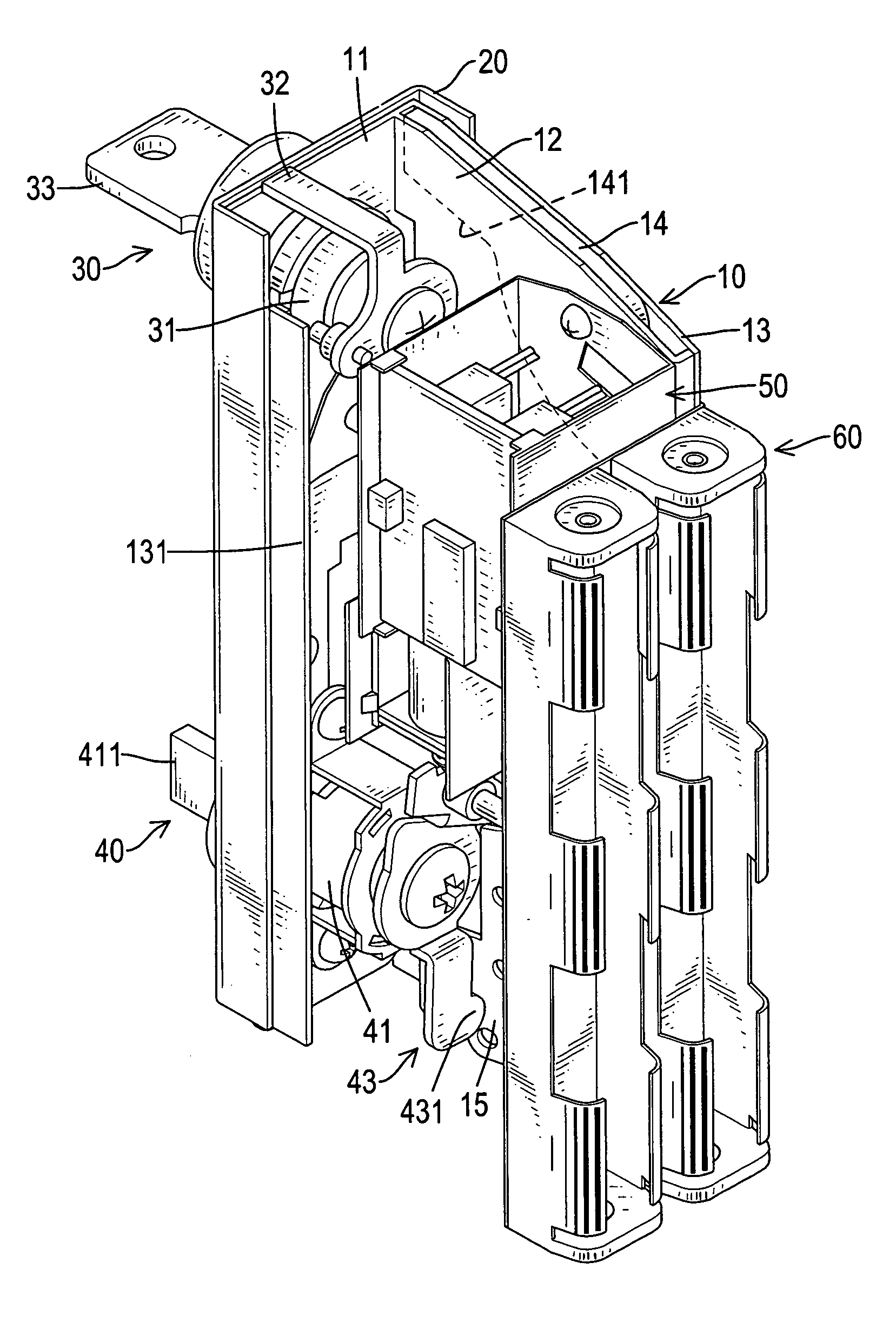
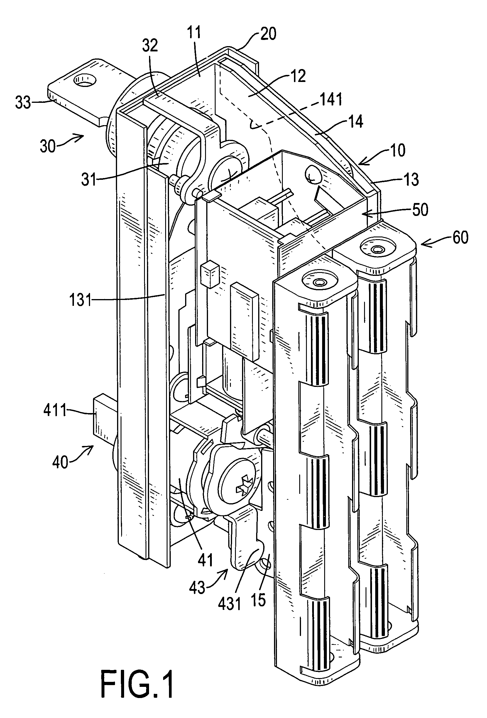
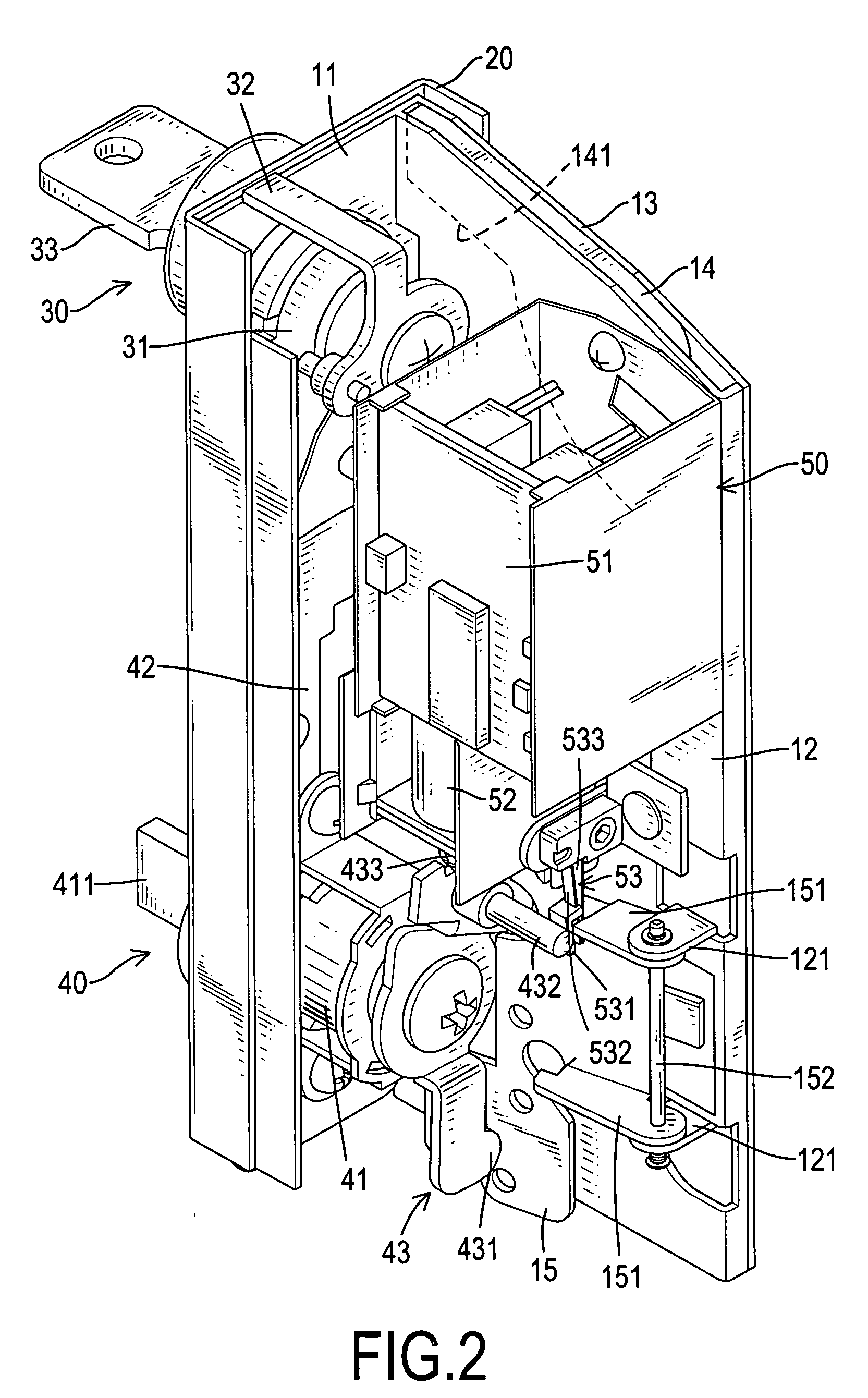
[0014]With reference to FIG. 1, a lock in accordance with the present invention for a locker has a housing (10), a front panel (20), a control locking device (30), a main locking device (40), an electrical controller (50) and a power supply (60).

[0015]The housing (10) has a bracket (11), a partition (12), a coin passage (14) and a pivoting spade (15).

[0016]The bracket (11) has a transverse panel, an elongated wing (13) and a short wing (131). The transverse panel has two mounting holes, a rear surface, two edges and a coin slot. The mounting holes are formed through the transverse panel. The coin slot is formed through the transverse panel. The elongated wing (13) is formed on and protrudes back perpendicular from the rear surface of the transverse panel at one edge and has an inside surface. The short wing (131) is formed on and protrudes back perpendicular from the inside surface of the transverse panel at the other edge parallel to the elongated wing (13).

[0017]With further refer...


PUM


Abstract

A lock for a locker has a housing, a front panel, a control locking device, a main locking device, an electrical controller and a power supply device. The main locking device has an operating knob to operate the lock for the locker. Therefore, when the operating knob is turned, the lock is locked or unlocked. Using an operating knob directly formed on the locking device is convenient.

Description

BACKGROUND OF THE INVENTION[0001]1. Field of the Invention[0002]The present invention relates to a lock, more particularly to a lock for a locker, which can be operated without a key.[0003]2. Description of the Related Art[0004]Lockable lockers are provided in many public places for use by the general public, and most of these lockers require payment for use. A conventional pay locker has a body, a door and a lock. The door is pivotally attached to the body. The lock is conventional, tends to be very complex, is mounted on the door and selectively engages the body, or vice versa, to lock the door and has a coin-activated enabling device, a locking mechanism and a key. A coin is inserted into the coin-activated enabling device to release the coin-activated enabling device. The key is mounted detachably in and locks or unlocks the locking mechanism when the key is rotated in the locking mechanism. When the key is rotated to lock the door after a coin has been inserted into the coin-ac...

Claims


Application Information

Patent Timeline
Patent Type & Authority Applications(United States)
IPC IPC(8): E05B65/44
CPCE05B47/0676E05B65/025E05B2047/0058G07F17/12G07F5/02G07F5/22E05B2047/0086Y10T70/5097
Inventor CHANG, HSUEH-LIANG
Owner CHANG HSUEH LIANG
Why Eureka
Try Eureka