Radio frequency navigation using frequency response matching

a frequency response matching and radio frequency technology, applied in direction finders, direction finders using radio waves, instruments, etc., can solve the problems of inaccurate accuracy, insufficient time elapse, and unreliable time of arrival techniques and other techniques

Inactive Publication Date: 2008-06-19
THE BOEING CO
View PDF9 Cites 31 Cited by
  • Summary
  • Abstract
  • Description
  • Claims
  • Application Information

AI Technical Summary

Problems solved by technology

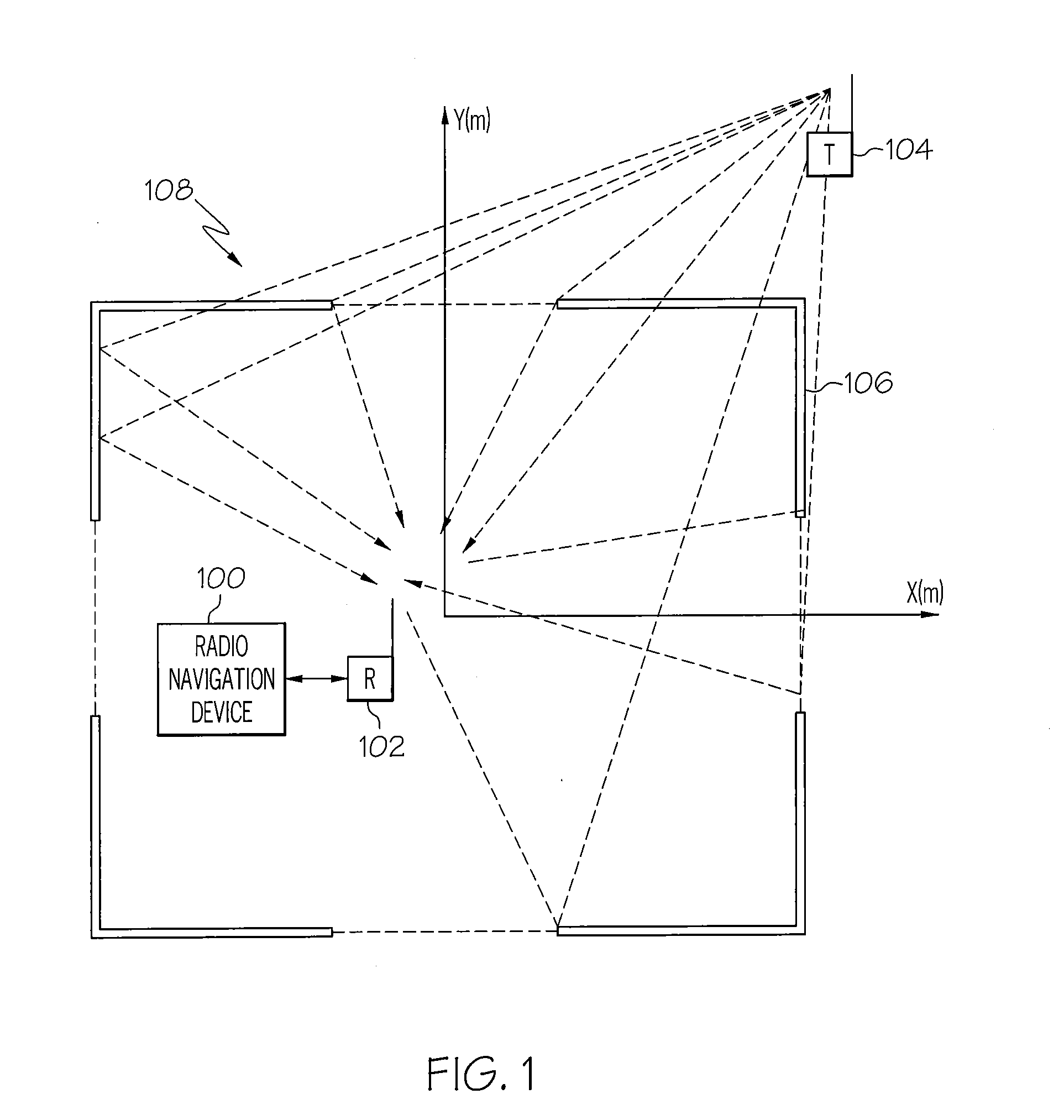
Determining a location of a device using radio navigation may be particularly challenging within a structure or other operating environment where the device is proximate to near field scattering objects that can cause time of arrival techniques and other techniques to be unreliable.
When a radio navigation receiver or the like is in the near field of one or more scattering objects, insufficient time may elapse between a line of sight (LOS) signal and non-line of sight (NLOS) signals, scattered by the scattering objects, to distinguish between these types of signals.
This may result in accuracy errors on the order of the distance between the receiver and the scattering objects.
When much higher positioning accuracy is needed, time of arrival techniques may be unreliable, especially when the signal bandwidth is limited.

Method used


Image

  • Radio frequency navigation using frequency response matching
  • Radio frequency navigation using frequency response matching
  • Radio frequency navigation using frequency response matching

Examples


Embodiment Construction

[0015]The following detailed description of embodiments refers to the accompanying drawings, which illustrate specific embodiments of the invention. Other embodiments having different structures and operations do not depart from the scope of the present invention.

[0016]As will be appreciated by one of skill in the art, the present invention may be embodied as a method, system, or computer program product. Accordingly, the present invention may take the form of an entirely hardware embodiment, an entirely software embodiment (including firmware, resident software, micro-code, etc.) or an embodiment combining software and hardware aspects that may all generally be referred to herein as a “circuit,”“module” or “system.” Furthermore, the present invention may take the form of a computer program product on a computer-usable storage medium having computer-usable program code embodied in the medium.

[0017]Any suitable computer usable or computer readable medium may be utilized. The computer...


PUM


Abstract

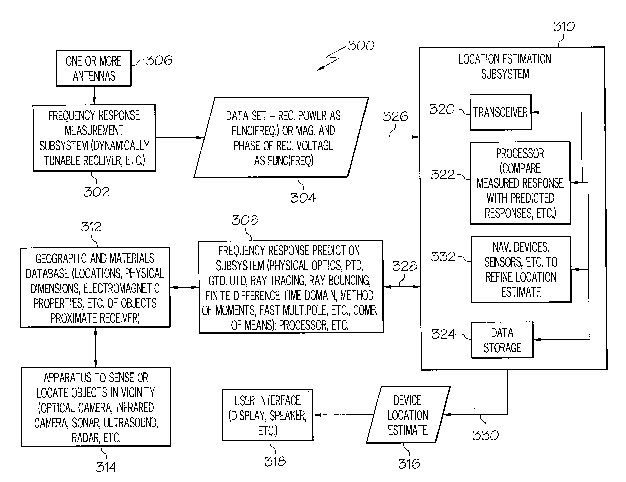
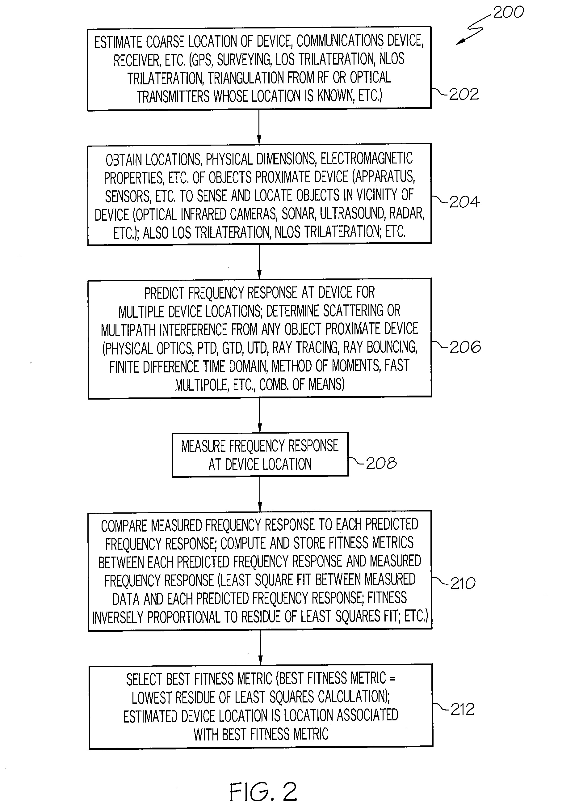
A method for radio navigation may include predicting a frequency response for each of a multiplicity of possible device locations. The method may also include measuring a frequency response at an actual device location. The method may further include matching the measured frequency response to one of the predicted frequency responses to determine an estimated device location, wherein the estimated device location corresponds to the possible device location associated with the one predicted frequency response that most closely matches the measured frequency response.

Description

BACKGROUND OF THE INVENTION[0001]The present invention relates to navigation and determining a location of a device, such as a communications device or the like and more particularly to radio frequency navigation or determining a location of a device using frequency response matching.[0002]Determining a location of a device using radio navigation may be particularly challenging within a structure or other operating environment where the device is proximate to near field scattering objects that can cause time of arrival techniques and other techniques to be unreliable. When a radio navigation receiver or the like is in the near field of one or more scattering objects, insufficient time may elapse between a line of sight (LOS) signal and non-line of sight (NLOS) signals, scattered by the scattering objects, to distinguish between these types of signals. This may result in accuracy errors on the order of the distance between the receiver and the scattering objects. When much higher pos...

Claims


Application Information

Patent Timeline
Patent Type & Authority Applications(United States)
IPC IPC(8): G01S3/02G01S5/02G01S19/25
CPCG01S5/0252G01S5/02528G01S5/14G01S5/02521
Inventor BORNHOLDT, JAMES M.
Owner THE BOEING CO
Why Eureka
Try Eureka