Cyclonic Separation Apparatus

US20080148694A1Inactive Publication Date: 2008-06-26HOOVER LIMITED
31 Cites 7 Cited by

Patent Information

Authority / Receiving Office
US · United States
Current Assignee / Owner
Publication Date
2008-06-26
Estimated Expiration
Not applicable · inactive patent

Smart Images

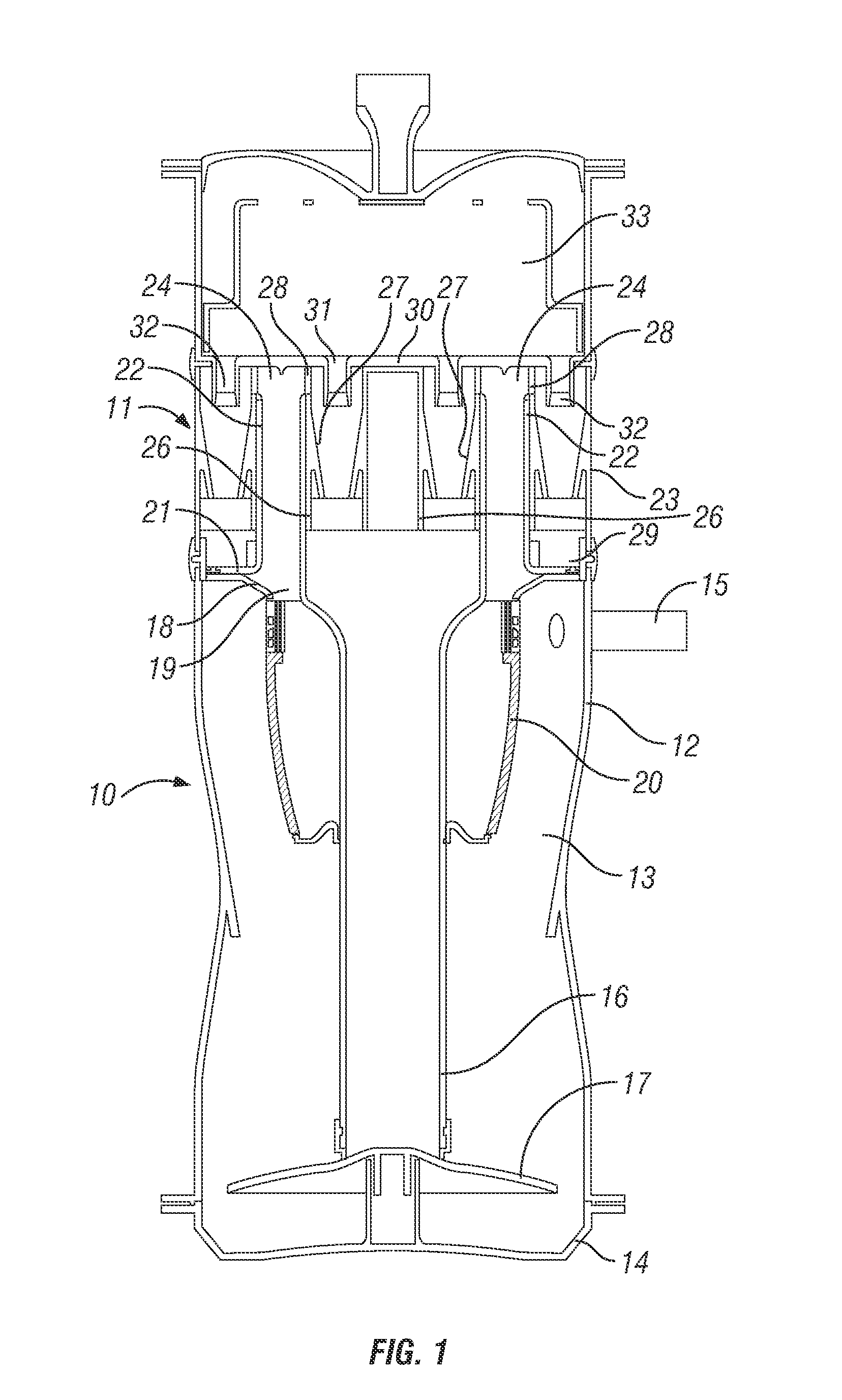
  • Figure 1
    Figure 1
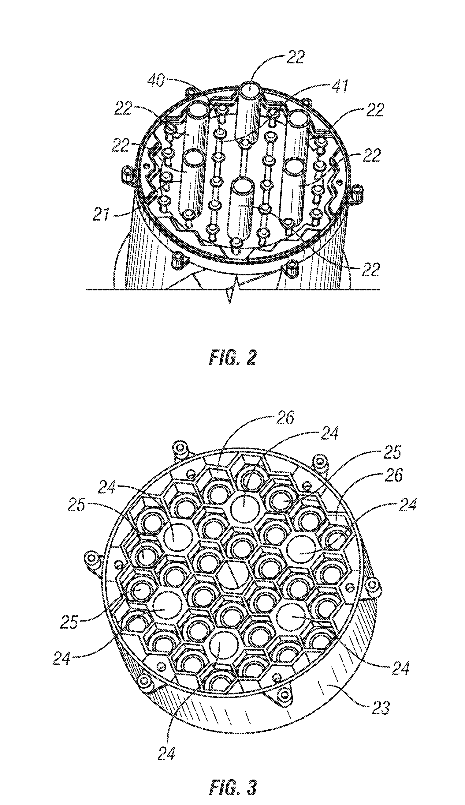
  • Figure 2
    Figure 2
  • Figure 3
    Figure 3
Patent Text Reader

Abstract

A cyclonic vacuum cleaner comprises a first stage 10 comprising a single cyclone separator for separating heavier dirt and dust particles and a second stage 11 comprising a plurality of cyclone separators 25 arranged in parallel in a plurality of groups, each group of cyclone separators 25 comprising a respective inlet duct 24, each inlet duct 24 being connected at its upstream end to the first stage 10 and at its downstream end to the cyclone separators 25 of its respective group.
Need to check novelty before this filing date? Find Prior Art

Description

BACKGROUND OF THE INVENTION

[0001] 1. Field of the Invention

[0002] This invention relates to cyclonic separation apparatus.

[0003] 2. Related Background Art

[0004] Cyclonic separators are well known apparatus for removing particles from a gas flow without the use of filters. Cyclone separators have found utility in the field of vacuum cleaners to separate dirt and dust from the airflow. It is well known that the separation efficiency of cyclonic separators is dependent upon the force which is applied to the particles in the airflow, in accordance with the following formula.f=2mv2 / d, where

[0005] f=the force applied to the particles

[0006] m=the mass of the particle

[0007] v=the flow velocity

[0008] d=the diameter of the cyclonic airflow

[0009] Thus it will be appreciated that the separation efficiency is inversely proportional to the diameter of the cyclone chamber, such that smaller diameter cyclones are more suited to separating lighter particles than larger cyclones.

[0010] Accordingly, it is well ...

Examples

Embodiment Construction

[0035]Referring to FIG. 1 of the drawings, there is shown the separation portion of an upright vacuum cleaner. The separation portion is mounted to a chassis (not shown) incorporating a handle, the lower end of the chassis being pivotally interconnected to a wheeled floor-cleaning head incorporating a rotatable agitator brush.

[0036]The separation portion comprises a generally cylindrical upright housing, which houses the first and second separation stages 10, 11 at its lower and upper ends respectively, the second stage 11 being fluidly connected downstream of the first stage 10.

[0037]The first stage 10 comprises a tubular side wall 12 defining a circular-section cyclone chamber 13. The lower end of the tubular side wall 12 is provided with a closure 14, which can be opened to allow separated dirt and dust to be emptied from the chamber 13.

[0038]An inlet duct 15 for carrying dirt and dust laden air from the floor cleaning head extends tangentially into the upper end of the tubular s...