Rapid delivery and/or receiving of fluids
What is Al technical title?
Al technical title is built by PatSnap Al team. It summarizes the technical point description of the patent document.
a fluid delivery and fluid technology, applied in the field of fluid delivery and/or fluid receiving, can solve the problems of complex procedures, inability to perform, and require sophisticated training of practitioners, and achieve the effects of improving the packing density of needles, improving the density of needles, and increasing the total number of microneedles
Active Publication Date: 2017-05-04
YOURBIO HEALTH INC
View PDF5 Cites 12 Cited by
Summary
Abstract
Description
Claims
Application Information
AI Technical Summary
This helps you quickly interpret patents by identifying the three key elements:
Problems solved by technology
Method used
Benefits of technology
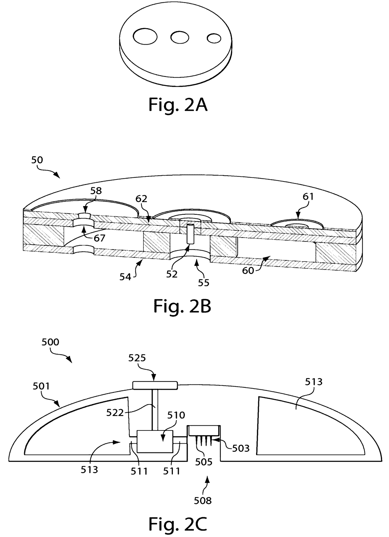
[0005]In one aspect of the invention, microneedles in an array may be arranged to maximize a density of microneedles per unit area of the array. For example, a number of microneedles in a circular array according to one embodiment of the invention may be about two times the number of microneedles in a rectangular array having the same footprint size. Improved density may be achieved in some embodiments by having microneedles arranged (while the microneedles are lying in a common plane and prior to bending a penetrating portion of the needles upward from the plane) so that the microneedles generally “point” towards at least one other microneedle in the array and such that the microneedles ore generally not parallel with each other. For example, in one embodiment, a method for forming an array of microneedles may include steps of providing a layer of material having opposed substantially planar sides, and etching the layer of material to define a plurality of microneedles. The microneedles may be formed from the layer such that bases of the microneedles are arranged at a periphery of a closed loop and each of the microneedles extends toward a center of the closed loop. Since the microneedles in this illustrative embodiment may point radially inwardly, the microneedles will generally not be parallel with each other (although some needles may be parallel with one or more other needles). This configuration has been found to make efficient use of material in the layer and provide a higher total number of microneedles for a given area than other arrangements, such as a rectangular array in which the microneedles are all parallel to each other. After forming the microneedles from the layer, the penetrating portions of the microneedles may be bent away from the bases (i.e., out of the common plane of the layer) so that the penetrating portions are arranged for insertion into skin or other material. That is, the penetrating portions may be bent upwardly from the common plane of the layer so that the penetrating portions are arranged at an angle relative to the plane of the closed loop.
[0006]In another illustrative embodiment, an array of microneedles may include a plurality of microneedles that each include a base portion and a penetrating portion. The base portions of the plurality of needles may be arranged at the periphery of a closed loop lying in a common plane, and the penetrating portions may extend at an angle away from the plane of the closed loop. Such an arrangement may help improve a packing density of needles for the array, e.g., by allowing the needles to be formed from a sheet of material while making efficient use of the material, and / or provide for an array with Improved material transfer properties, e.g., by allowing the microneedles to provide a flow channel for fluid exiting from skin penetrated by the needles.
[0007]In another aspect of the invention, the microneedle arrangement includes a first plurality of microneedles that each include a base portion and a penetrating portion, the base portions of the first plurality of microneedles being arranged at the periphery of a first closed loop lying in a plane, the penetrating portions of the first plurality of microneedles each extending at a respective angle away from the plane of the first closed loop. The arrangement also includes a second plurality of microneedles that each include a base portion and a penetrating portion, the base portions of the second plurality of microneedles being arranged at a periphery of a second closed loop lying in the plane, the second closed loop being larger than, and surrounding, the first closed loop, the penetrating portions of the second plurality of microneedles each extending at a respective angle away from the plane of the second closed loop. This arrangement may further increase the packing density of needles. In some illustrative embodiments, the closed loops are circles. In one illustrative embodiment, the closed loops are concentric circles.
Problems solved by technology
However, such procedures are complicated and require sophisticated training of practitioners, and often cannot be done in non-medical sellings.
Method used
Image
Click on the blue label to locate the original text in one second.
Reading with bidirectional positioning of images and text.
Examples
Embodiment Construction
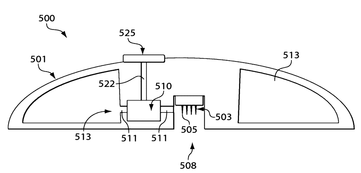
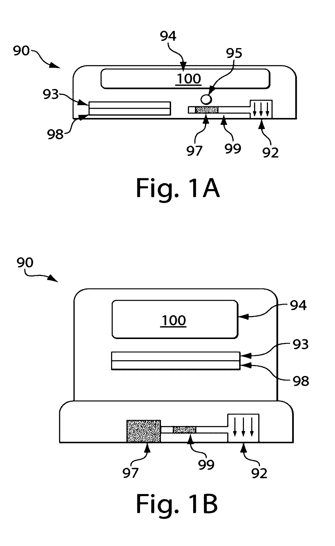
[0042]The present invention generally relates to systems and methods for receiving a substance from a subject, e.g. received from the skin and / or from beneath the skin of the subject, and / or for delivering a substance to a subject, e.g. delivering a substance to the skin and / or to a location beneath the skin of a subject. Throughout the application, the phrase “from the skin” is used to mean from the top or outer surface of the skin, from within the skin, and / or from beneath the skin. Likewise, “to the skin” is used to mean to the top or outer surface of the skin, to within the skin, and / or to beneath the skin. The device, in some cases, may be interfaced with external equipment to determine an analyte contained within a fluid contained within or collected by the device. For example, the device may be mounted on an external holder, the device may include a port for transporting fluid out of the device, the device may include a window for interrogating a fluid contained within the de...
PUM
Property
Measurement
Unit
skin-penetration area
aaaaa
aaaaa
angle
aaaaa
aaaaa
angle
aaaaa
aaaaa
Abstract
The present invention generally relates to systems and methods for delivering and / or receiving a substance or substances such as blood, from subjects, e.g., from the skin and / or from beneath the skin. In one aspect, the present invention is generally directed to devices and methods for receiving or extracting blood from a subject, e.g., from the skin and / or from beneath the skin, using devices containing a fluid transporter (for example, one or more microneedles), and a storage chamber having an internal pressure less than atmospheric pressure prior to receiving blood. In some cases, the device may be self-contained, and in certain instances, the device can be applied to the skin, and activated to receive blood from the subject. The device, or a portion thereof, may then be processed to determine the blood and / or an analyte within the blood, alone or with an external apparatus. For example, blood may be received from the device, and / or the device may contain sensors or agents able to determine the blood and / or an analyte suspected of being contained in the blood. In another aspect, the present invention is generally directed to arrangements of skin insertion objects such as microneedles and methods of forming and arranging skin insertion objects. Other aspects of the present invention are directed at other devices for receiving blood (or other bodily fluids, e.g., interstitial fluid), kits involving such devices, methods of making such devices, methods of using such devices, and the like.
Description
RELATED APPLICATIONS[0001]This application claims the benefit of U.S. Provisional Patent Application Ser. No. 61 / 367607, filed Jul. 26, 2010, entitled “Rapid Delivery and / or Withdrawal of Fluids,” by Chickering, et al. This application is incorporated herein by reference.FIELD OF INVENTION[0002]The present invention generally relates to systems and methods for delivering and / or receiving a substance or substances such as blood and / or drugs, with respect to subjects, e.g., at and / or beneath the skin, and in some cases, with relatively little pain.BACKGROUND[0003]Phlebotomy or venipuncture is the process of obtaining intravenous access for the purpose of intravenous therapy or obtaining a sample of venous blood. This process is typically practiced by medical practitioners, including paramedics, phlebotomists, doctors, nurses, and the like. Substantial equipment is needed to obtain blood from a subject, including the use of evacuated (vacuum) tubes, e.g., such as the Vacutainer™ (Becto...
Claims
Application Information
Patent Timeline
Application Date:The date an application was filed.
Publication Date:The date a patent or application was officially published.
First Publication Date:The earliest publication date of a patent with the same application number.
Issue Date:Publication date of the patent grant document.
PCT Entry Date:The Entry date of PCT National Phase.
Estimated Expiry Date:The statutory expiry date of a patent right according to the Patent Law, and it is the longest term of protection that the patent right can achieve without the termination of the patent right due to other reasons(Term extension factor has been taken into account ).
Invalid Date:Actual expiry date is based on effective date or publication date of legal transaction data of invalid patent.
Patent Type & Authority Applications(United States)