Cyclonic separation apparatus

a technology of cyclonic separation and cyclone separator, which is applied in the field of cyclonic separation apparatus, can solve the problems of reducing separation efficiency, small size, and easy blockage, and achieves the effect of maximising maximizing the density of cyclone separator, and large cyclonic separator

Inactive Publication Date: 2011-06-07
HOOVER LIMITED
View PDF43 Cites 15 Cited by
  • Summary
  • Abstract
  • Description
  • Claims
  • Application Information

AI Technical Summary

Benefits of technology

[0014]The combined cross-sectional area of the plurality of inlet ducts is large and hence the ducts do not cause a restriction in the air flow and as such the separation efficiency is maximised. Also, since the cyclones are arranged in groups, with each inlet duct only feeding some cyclone separators of the apparatus, the need for complex and small secondary ducts is avoided and the apparatus is thus less susceptible to blockage. Furthermore, any pressure drop is minimised because the inlet ducts can positioned be in close proximity to the cyclone separators.
[0017]Preferably, the radial distance between the longitudinal axis of each inlet duct and each cyclone separator of their respective group is substantially equal, thereby ensuring that the airflow path to each cyclone separator is substantially the same. This helps to ensure that the volume of air flowing along each inlet duct is substantially equal, so that the dirt loadings on each cyclone are the same.
[0024]Preferably, the cyclone separators of each group are disposed at selected positions along an arcuate line centred about the longitudinal axis of the inlet duct of the group. An advantage of this arrangement is that it maximises the density of the cyclonic separators and thereby enables a larger cyclonic separators to be used than permitted by prior arrangements.
[0025]Preferably, the arcuate lines of adjacent groups are interleaved to maximise the density of the cyclone separators of the apparatus.

Problems solved by technology

One disadvantage of the above-mentioned arrangement is that the main duct can cause a restriction in the air flow and the resultant drop in air flow velocity reduces the separation efficiency.
Another disadvantage of the above-mentioned arrangement is that the secondary ducts are complex, small and susceptible to blockage.

Method used


Image

  • Cyclonic separation apparatus
  • Cyclonic separation apparatus
  • Cyclonic separation apparatus

Examples


Embodiment Construction

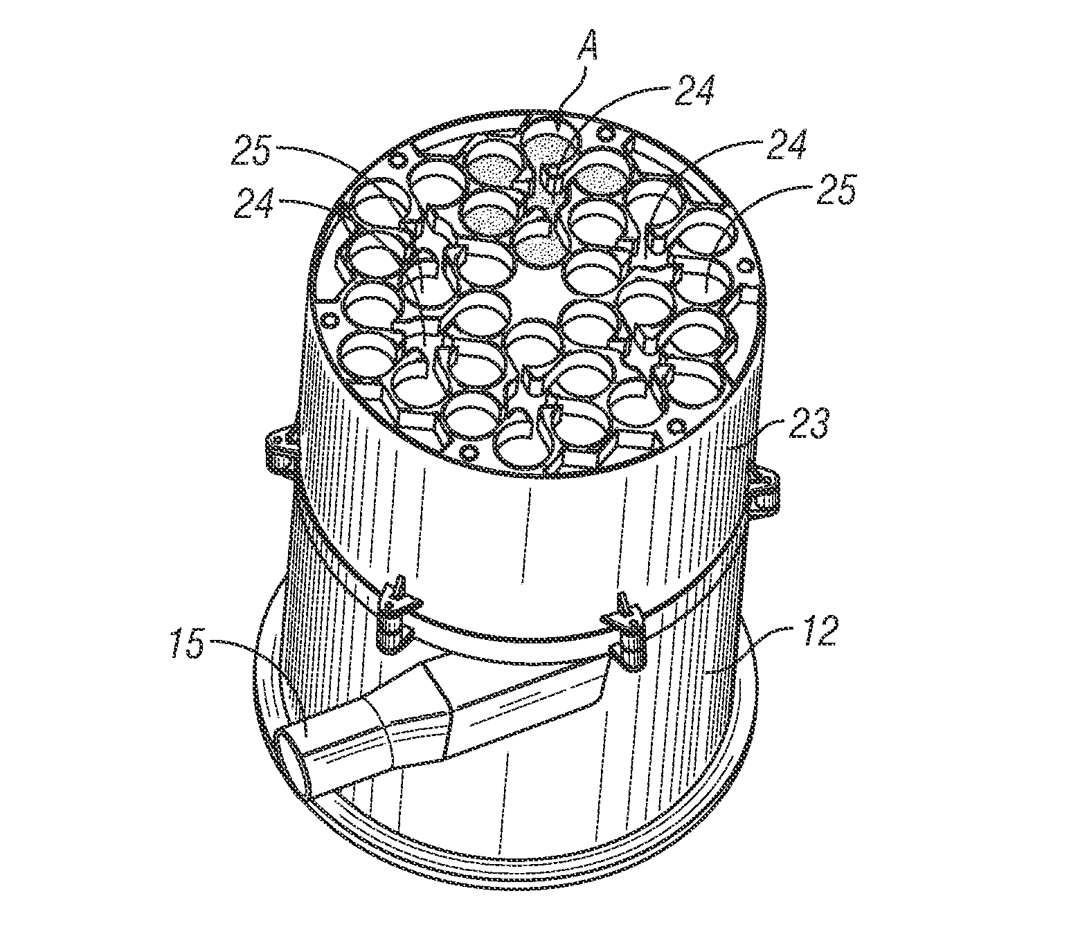
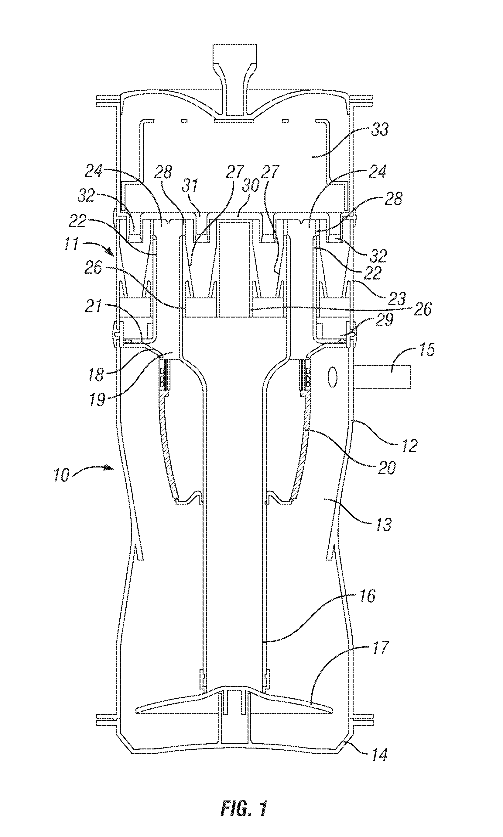
[0035]Referring to FIG. 1 of the drawings, there is shown the separation portion of an upright vacuum cleaner. The separation portion is mounted to a chassis (not shown) incorporating a handle, the lower end of the chassis being pivotally interconnected to a wheeled floor-cleaning head incorporating a rotatable agitator brush.

[0036]The separation portion comprises a generally cylindrical upright housing, which houses the first and second separation stages 10, 11 at its lower and upper ends respectively, the second stage 11 being fluidly connected downstream of the first stage 10.

[0037]The first stage 10 comprises a tubular side wall 12 defining a circular-section cyclone chamber 13. The lower end of the tubular side wall 12 is provided with a closure 14, which can be opened to allow separated dirt and dust to be emptied from the chamber 13.

[0038]An inlet duct 15 for carrying dirt and dust laden air from the floor cleaning head extends tangentially into the upper end of the tubular s...


PUM

PropertyMeasurementUnit
diameteraaaaaaaaaa
diameteraaaaaaaaaa
radial distanceaaaaaaaaaa

Abstract

A cyclonic vacuum cleaner comprises a first stage 10 comprising a single cyclone separator for separating heavier dirt and dust particles and a second stage 11 comprising a plurality of cyclone separators 25 arranged in parallel in a plurality of groups, each group of cyclone separators 25 comprising a respective inlet duct 24, each inlet duct 24 being connected at its upstream end to the first stage 10 and at its downstream end to the cyclone separators 25 of its respective group.

Description

BACKGROUND OF THE INVENTION[0001]1. Field of the Invention[0002]This invention relates to cyclonic separation apparatus.[0003]2. Related Background Art[0004]Cyclonic separators are well known apparatus for removing particles from a gas flow without the use of filters. Cyclone separators have found utility in the field of vacuum cleaners to separate dirt and dust from the airflow. It is well known that the separation efficiency of cyclonic separators is dependent upon the force which is applied to the particles in the airflow, in accordance with the following formula.f=2mv2 / d, where[0005]f=the force applied to the particles[0006]m=the mass of the particle[0007]v=the flow velocity[0008]d=the diameter of the cyclonic airflow[0009]Thus it will be appreciated that the separation efficiency is inversely proportional to the diameter of the cyclone chamber, such that smaller diameter cyclones are more suited to separating lighter particles than larger cyclones.[0010]Accordingly, it is well ...

Claims


Application Information

Patent Timeline
Patent Type & Authority Patents(United States)
IPC IPC(8): B01D45/12
CPCA47L9/1641A47L9/165B04C5/28B04C5/12B04C5/14A47L9/1658A47L9/16A47L9/1608A47L9/1616B04C5/24
Inventor SMITH, DAVID BENJAMIN
Owner HOOVER LIMITED
Why Eureka
Try Eureka