Highly effective slurry phase bed reactor

A technology of reactor and slurry bed, which is applied in the field of slurry bed reactor, can solve the problems of abnormal operation of the reactor and prone to bias flow, etc., and achieve the effects of high reactivity, low flow bias and fast flow speed

Inactive Publication Date: 2005-03-16
TAIYUAN UNIV OF TECH
View PDF0 Cites 34 Cited by
  • Summary
  • Abstract
  • Description
  • Claims
  • Application Information

AI Technical Summary

Problems solved by technology

[0005] The purpose of the present invention is to overcome the abnormal operation of the reactor caused by the large amount of catalyst and solvent carried in the existing slurry bed reactor and the easy occurrence of bias flow, channel flow and dead bed

Method used


Image

  • Highly effective slurry phase bed reactor

Examples


Embodiment approach 1

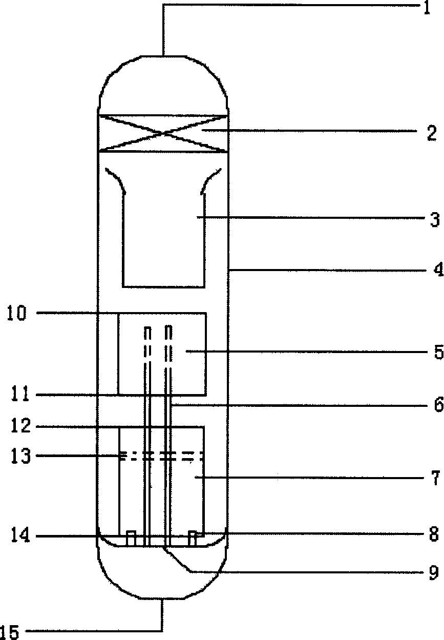
[0017] The high-efficiency slurry bed reactor of the present invention consists of a solid-liquid separator 2, a variable-diameter inner sleeve 3, a reactor outer sleeve 4, a heat exchanger 5 with internal components, a gas riser 6 with nozzles, and a heating and gas distribution function. The inner sleeve 7, the anti-blocking nozzle 8, the nozzle installation plate 9 of the head type structure and the secondary distribution plate 13 are formed. In this reactor, the internal components for realizing the internal circulation of the slurry are arranged, including the reducing sleeve 3, with The inner sleeve 7 for heating and gas distribution, the nozzle mounting plate 9 of the head type structure, the gas riser 6 for uniformly distributing the gas along the axial direction of the reactor, the secondary gas distribution plate 13 for realizing the secondary distribution of the gas, and the solid The liquid separator 2 constitutes. The anti-blocking nozzle 8 outlet has a spherical ...

Embodiment approach 2

[0020] In the high-efficiency slurry bed reactor of the present invention, the outlet of the anti-clogging nozzle 8 has a spherical body to prevent the backflow of the slurry, and its diameter is 1.2 times that of the nozzle throat. The nozzle mounting plate 9 of the head type structure is tangent to the inner wall of the reactor, and forms a smooth slurry return channel with the outer wall of the reactor. The internal component sleeve 7 with heating effect is made of coiled tubes, and the distance between the coiled tubes changes from zero to the diameter of the coiled tubes from bottom to top. The barrel diameters of the variable diameter inner sleeve 3, the heat exchanger 5 with internal components and the internal component inner sleeve 7 with heating function change from 0.5 times the reactor diameter to 0.9 times the reactor diameter from bottom to top. Gas riser 6 is installed in the inside of the reactor and directly links to each other with feed gas inlet 15, and the ...

Embodiment approach 3

[0023] In the high-efficiency slurry bed reactor of the present invention, the outlet of the anti-clogging nozzle 8 has a spherical body to prevent the backflow of the slurry, and its diameter is 1.3 times that of the nozzle throat. The nozzle mounting plate 9 of the head type structure is tangent to the inner wall of the reactor, and forms a smooth slurry return channel with the outer wall of the reactor. The internal component sleeve 7 with heating effect is made of coiled tubes, and the distance between the coiled tubes changes from zero to the diameter of the coiled tubes from bottom to top. The barrel diameters of the variable-diameter inner sleeve 3, the heat exchanger 5 with internal components and the internal component inner sleeve 7 with heating function change from 0.6 times the diameter of the reactor to 1 times the diameter of the reactor from bottom to top. Gas riser 6 is installed in the inside of the reactor and directly links to each other with feed gas inlet ...


PUM


Abstract

The invention relates to a kind of efficient reactor with paddle bed, which belongs to the chemical machinery field. It is composed mainly with the solid and liquid separator, the inner tube that the track is changeable, the reactor cover, the heat exchanger with an internal component, the riser with the spray nozzle, the inner-tube tank that has the heating and gas distribution function, the spray nozzle for protecting from choking, the mounting plate of the spray nozzle, the heat exchanger, the outlet of the heating coil, the quadratic distribution plate, the heating coil and so on. The beneficial effictiveness of the invention can be described as follows: the reactor and the distributor can't block up easily; the gas and the liquid can be mixed evenly; the reactive efficiency is high; the carrying amount of the catalyst and the solvent is so bit that it can not occur the bias current, channeling and dead bed; the size running quickly, and the viscosity of the size in the reactor is identical generally; the reactor can be shifted out in time, and especially in the stage of the catalytic, reducing and intensifying, it can realize to operate the reactor steadily; otherwise, the distribution of the virgin gas in the reactor along the axle is in agreement on the concentration of the catalyst, so that can make the catalyst have the most activity, and then it can be make the full use of the reactor space.

Description

1. Technical field [0001] The invention relates to a slurry bed reactor suitable for producing chemicals such as dimethyl ether and methanol, belonging to the field of chemical machinery. 2. Background technology [0002] Slurry bed reactor is a new type of chemical reaction equipment. It uses raw material gas as the power source of reaction mixing, uses inert solvent as the carrier, and disperses and suspends the catalyst in the solvent for reaction. This type of reaction equipment has no mechanical Stirring, so it can run leak-free at high temperature and pressure. Since the inert solvent is used as the carrier of the dispersed catalyst, the heat capacity is large, which is conducive to the stability of the reaction temperature. Due to the strong disturbance of the gas in the bed, the heat of reaction can be removed in time, avoiding hot spots in the bed and prolonging the life of the catalyst. . The existing slurry bed reactor is often blocked due to the restriction of ...

Claims


Application Information

Patent Timeline
Patent Type & Authority Applications(China)
IPC IPC(8): B01J8/22
Inventor 谢克昌姜少华黄伟田原宇
Owner TAIYUAN UNIV OF TECH
Why Eureka
Try Eureka