Method and apparatus for performing high-density DTMF, MF-R1, MF-R2 detection

a detection method and high-density technology, applied in electrical equipment, substation equipment, interconnection arrangements, etc., can solve the problems of still inefficient dtmf context and achieve significant computational overhead for filtering, reduce computational complexity, and accelerate data acquisition

Inactive Publication Date: 2006-08-08
TELLABS OPERATIONS
View PDF5 Cites 11 Cited by
  • Summary
  • Abstract
  • Description
  • Claims
  • Application Information

AI Technical Summary

Benefits of technology

[0009]Although using FIR MRF filters is a fine idea, it is still inefficient in the context of DTMF due to the aforementioned reasons. For sufficient band isolation, a large number of coefficients might be necessary, and a high number of memory locations are necessary to store the filter his

Problems solved by technology

Although using FIR MRF filters is a fine idea, it is still inefficient in the context of DTMF due to the aforementioned reasons.
For sufficient band isolation, a large number of coefficients mi

Method used


Image

  • Method and apparatus for performing high-density DTMF, MF-R1, MF-R2 detection
  • Method and apparatus for performing high-density DTMF, MF-R1, MF-R2 detection
  • Method and apparatus for performing high-density DTMF, MF-R1, MF-R2 detection

Examples


case1

[0078]Case⁢⁢1:⁢0.14≤E0E1≤7.08

case 1

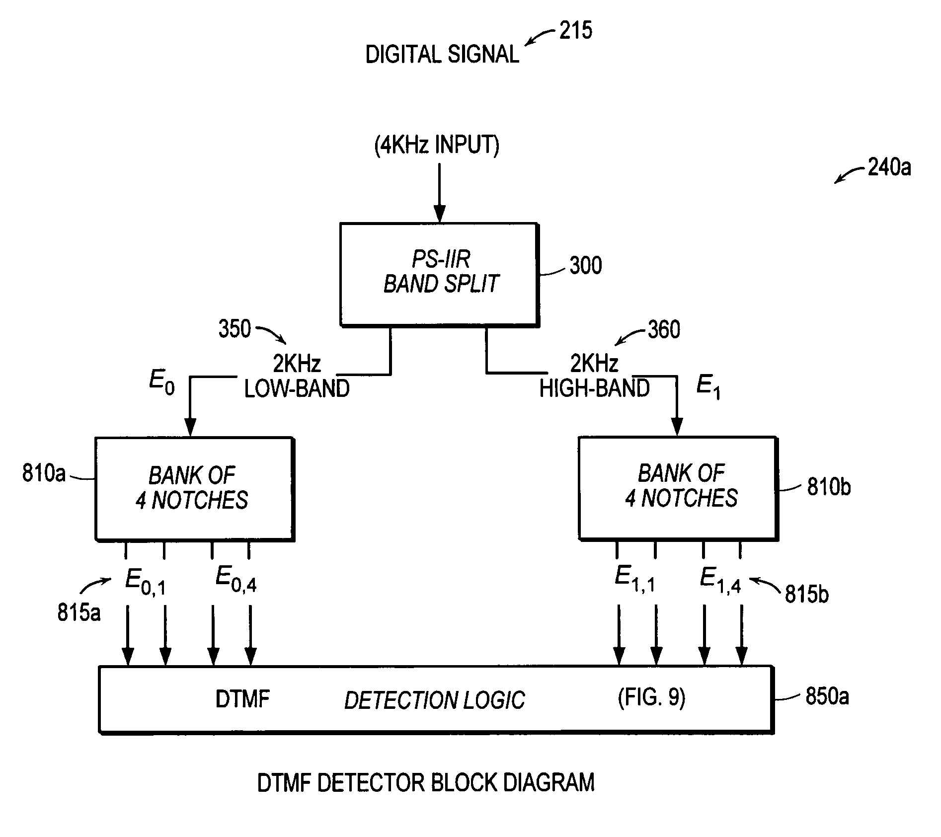
[0079 corresponds to the upper and lower subband energies being within + / −8.5 dB of each other. In this case, there is a high likelihood that tones are present in both the upper and lower subbands. The MF detector 850b then proceeds exactly as in the case of DTMF, picking one tone from each subband. The bandwidth test is then performed using the lowest output energies from the upper and lower subband notches, as determined in steps 925c, 925b, respectively. If E0>E0,1α1 (step 945a) and E1>E1,uαu (step 930a), where E0,1 and E1,u are the minimum output energies for the lower and upper subbands respectively, then, in step 950a, the MF detector 850b picks the digit referenced by the two tones.

case2

[0080]Case⁢⁢2:⁢E0E1>7.08

[0081]FIG. 11B is a flow diagram of an embodiment of a process of Case 2 of the MF detector. In Case 2, it may be that either (i) there is a twist larger then +8.5 dB in the MF signal (with tones present in both subbands) or (ii) all the energy is present in the upper subband. Case 2 then searches for the lowest two output energies, Eo,u1 (step 925d) and Eo,u2 (step 925e) from the four upper subband frequencies.

[0082]The first test (step 936a) checks to see how noisy the signal is. If

[0083]E0,u1+Eo,u2E01.35,

the signal is assumed to be relatively noise free. The rationale behind the test of step 936a is that as the noise level in the signal rises (noise in this case being any signal that is not an MF frequency tone), the ratio of

[0084]E0,u1+Eo,u2E0

gets closer and closer to 2.00. For a white noise signal, and using notches of infinitesimal width, the ratio approaches 2.00. On the other hand, with no background noise (i.e. only tonal energy), the ratio approache...


PUM


Abstract

Detectors determine the presence of valid sinusoids for DTMF, MF-R1 and MF-R2 protocols for encoding dialed digits. The detectors split electrical signals into subbands. Energies within the subbands are analyzed to determine a presence of sinusoids corresponding to frequencies of dialed digits. In one embodiment, the detectors comprise a PS-IIR filter to split the electrical signal into the subbands. The detectors further comprise at least one bank of filters, such as notch filters, corresponding to the number of possible relevant frequencies within the respective subbands. The detectors further comprise detection logic comprising tests, which may include analyzing the output(s) from the bank of filters. Optionally, a preclassifier is employed to predetermine which filters in the banks of filters are to be executed. The detectors, typically deployed in digital signal processors, allow for an increase in the density of detectors and provide robust performance in talk-off situations.

Description

BACKGROUND OF THE INVENTION[0001]The information age has increased the number of users using data communication systems. Initially, voice was the primary signal carried by phone lines. Next, facsimile (i.e., fax) machines became a popular means for transferring information, though typically restricted to business environments. Recently, with the advent of the Internet, data communications between and among electronic devices has become a common mode of communications for both businesses and individuals. The increase in mode, user group, and usage has driven the telecommunications industry in general, and service providers in particular, to expand capacity. One of the limiting factors of service capacity is the size of detectors for determining dialed digits by various dialing protocols, such as DTMF.[0002]Detection of the dialed digits at the beginning of a phone connection is as old as the PSTN (Public Switched Telephone Network) itself. The requirements are well defined and unders...

Claims


Application Information

Patent Timeline
IPC IPC(8): H04M1/00H04L29/06
CPCH04L65/607H04L29/06027H04L65/70H04L65/1101
Inventor TANRIKULU, O{HACEK OVERGUPTA, SIDD
Owner TELLABS OPERATIONS
Why Eureka
Try Eureka