Data display system to facilitate pattern recognition and classification

a data display and pattern recognition technology, applied in the field of pattern recognition, can solve the problems of adding significant computational overhead to a multi-dimensional data set, and achieve the effects of facilitating interconnected representation, reducing visual distractions for viewers, and significant computational overhead

Inactive Publication Date: 2008-03-13
BRANLY ROLANDO
View PDF6 Cites 2 Cited by
  • Summary
  • Abstract
  • Description
  • Claims
  • Application Information

AI Technical Summary

Benefits of technology

[0007] A signal data display system can be used to monitor a live or pre-recorded data stream with the aim of determining instances in one dimensional data when the process generating the signal or numerical sequence has changed its fundamental characteristics. Since dynamic and physical processes are often generated through vibrations and oscillations viewing and monitoring both a signal and its representation in frequency space can be advantageous to human operator classification of data sets. Because it is difficult for a human operator to monitor two displays at once it is valuable to generate a third display that illustrates the relationship between a data set in one domain and its corresponding frequency domain. For example: the time and frequency domain, or the space and spatial frequency domain. This can add significant computational overhead for a multi-dimensional data set. For this reason this specification presents the one dimensional case. Multi-dimensional cases can be handled by parsing the data to generate a set of one dimensional data sets. The display system described uses hexagonal display regions that lend themselves to a graphical representation that facilitates an interconnected representation and decreases visual distractions for viewer.

Problems solved by technology

This can add significant computational overhead for a multi-dimensional data set.

Method used


Image

  • Data display system to facilitate pattern recognition and classification
  • Data display system to facilitate pattern recognition and classification
  • Data display system to facilitate pattern recognition and classification

Examples


Embodiment Construction

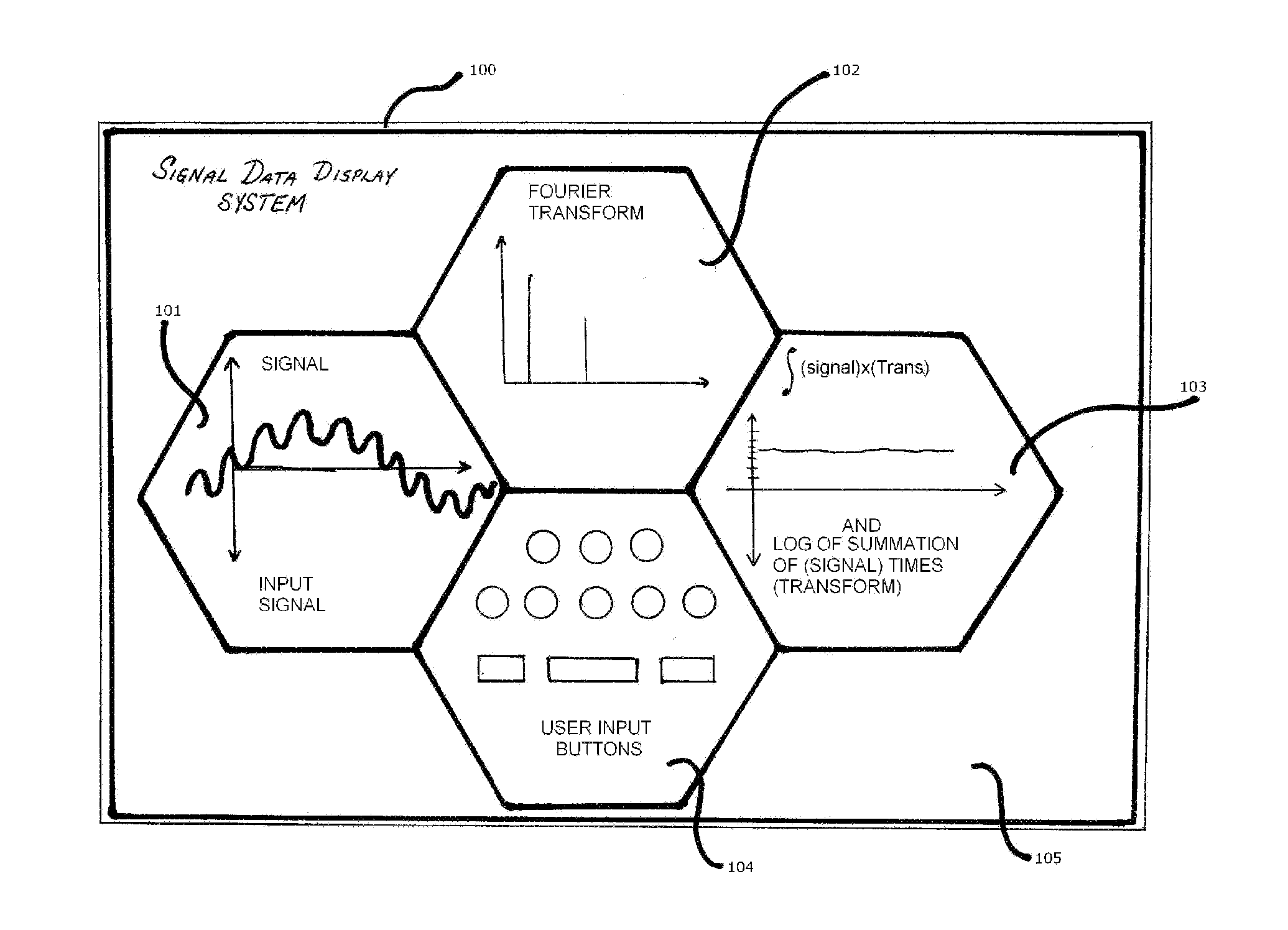
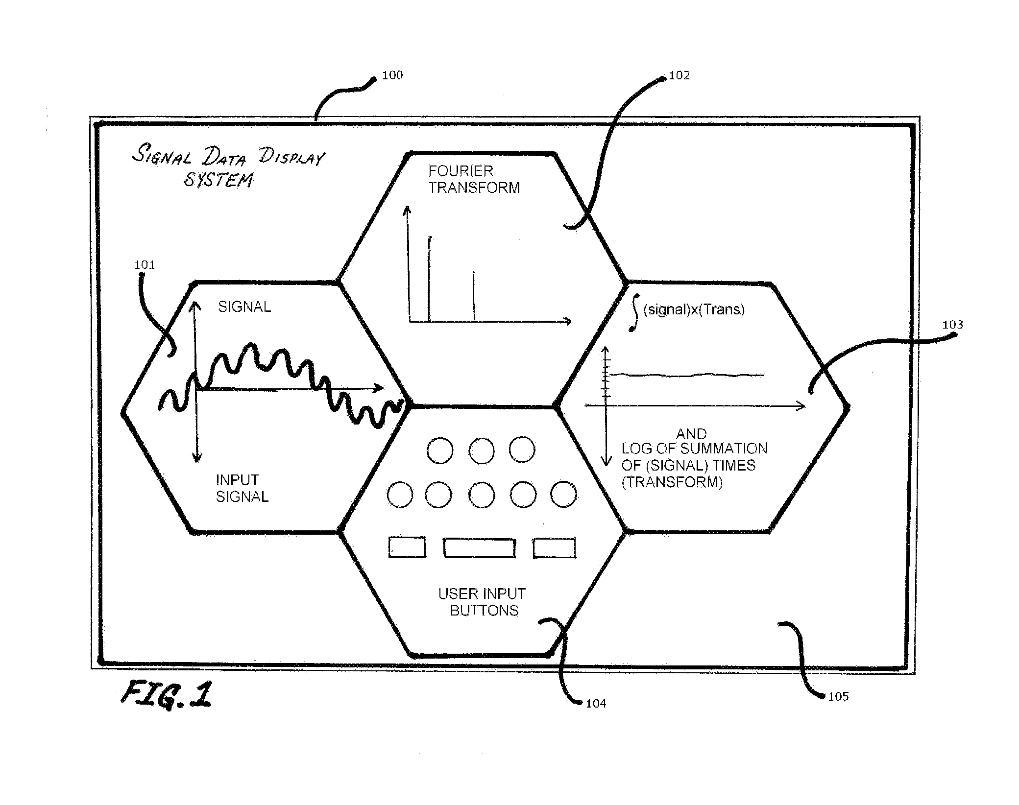
[0010]FIG. 1. illustrates an example of the preferred embodiment of a signal data display system 100. The system can be implemented on many varieties of computer monitors and display systems available in the industry such as cathode ray tubes (CRT's) or liquid crystal displays (LCD's). The display system 100 is comprised of several regions 101,102,103,104 and 105 (seen in FIG. 1.) that interconnect in order to facilitate viewing by a human operator monitoring “live” streaming data, or a pre-recorded one dimensional data set.

[0011] Region 101 illustrates the incoming signal obtained from a probe that outputs a voltage within a specified range, or the data sequence or numerical sequence from a digital computer file.

[0012] The display region 102 presents the Fourier transform or wavelet transform to the viewer. The display region 103 presents the viewer with the integral of the one dimensional signal times its transform (Fourier or wavelet) represented by a graphical and numerical di...


PUM


Abstract

A data display system and method to facilitate pattern recognition is disclosed. The display system can be used to monitor a live or pre-recorded data stream with the aim of determining instances in one dimensional data when the process generating the signal or numerical sequence has changed its fundamental characteristics. This is done by allowing a human operator to monitor and view data sets, along with their Fourier transforms and wavelet transforms on the same display system that emphasizes the relationship between them. The operator or viewer can make classification decisions based on his or her personal pre-established threshold criteria. The display system described uses hexagonal display regions that lend themselves to a graphical representation that facilitates an interconnected representation and decreases visual distractions for the viewer.

Description

TECHNICAL FIELD [0001] The present invention relates to pattern recognition and, more particularly to a data display configuration that facilitates viewing an input signal and its mathematical transform with human operator input. BACKGROUND OF THE INVENTION [0002] Pattern recognition systems are utilized in many areas of technology. Often times the process involves real time or nearly real time data viewed by an operator that aims to classify the input signals by comparing some of their parameters with pre-established numerical thresholds. [0003] A human operator viewing a computer screen can benefit from a display system that shows the signal and its Fourier and wavelet transform together on the same screen along with a quick check method that indicates sudden changes in the fundamental system generating the signal. If a time dependent or other one dimensional signal remains fundamentally the same, the mathematical integral of the product of the signal times its Fourier transform w...

Claims


Application Information

Patent Timeline
Patent Type & Authority Applications(United States)
IPC IPC(8): G09G5/22G06T11/20
CPCG06K9/6253G06K9/00523G06F2218/08G06F18/40
Inventor BRANLY, ROLANDO
Owner BRANLY ROLANDO
Why Eureka
Try Eureka