Method for forming a 3D kinematic deformation model of a sedimentary basin

a sedimentary basin and kinematic deformation technology, applied in the field of 3d kinematic deformation models of sedimentary basins, can solve the problems of limited 2d or pseudo-3d> models, complex formulations with substantial calculating time,

Inactive Publication Date: 2003-07-22
INST FR DU PETROLE
View PDF4 Cites 81 Cited by
  • Summary
  • Abstract
  • Description
  • Claims
  • Application Information

AI Technical Summary

Problems solved by technology

However, these models lead to very complex formulations that have substantial calculating time.
There are other 2D or

Method used


Image

  • Method for forming a 3D kinematic deformation model of a sedimentary basin
  • Method for forming a 3D kinematic deformation model of a sedimentary basin
  • Method for forming a 3D kinematic deformation model of a sedimentary basin

Examples


Embodiment Construction

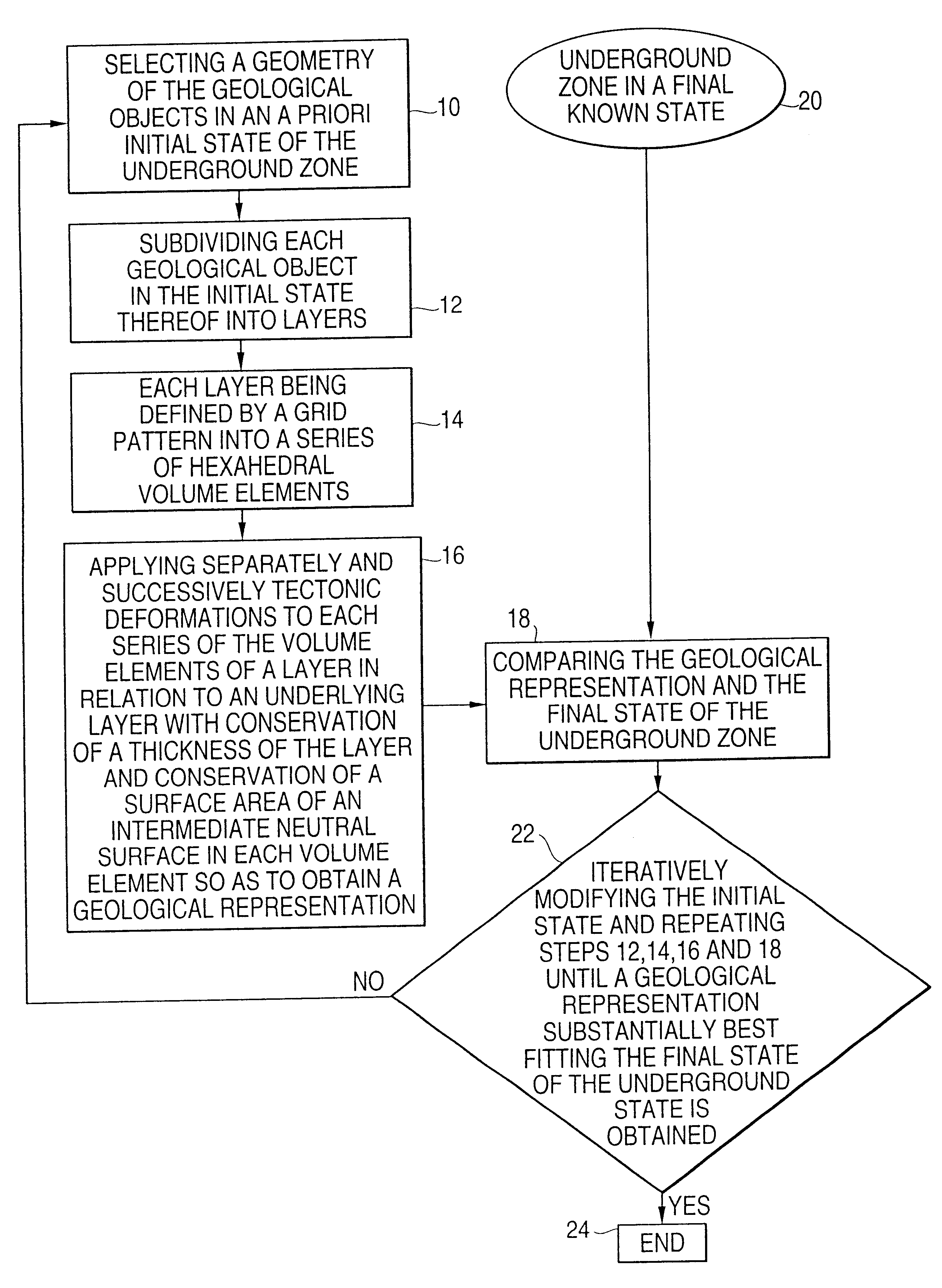
Principle of the Model

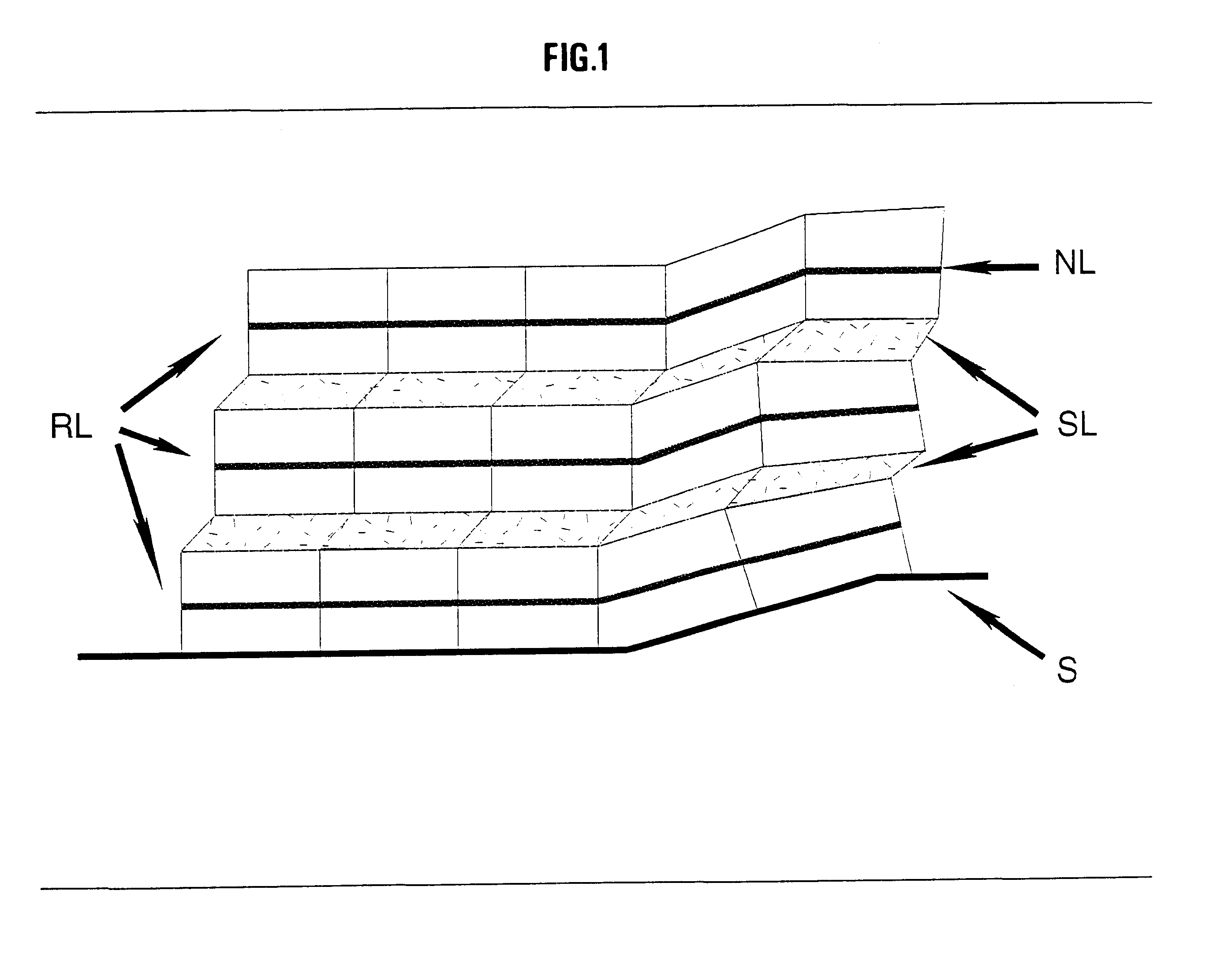
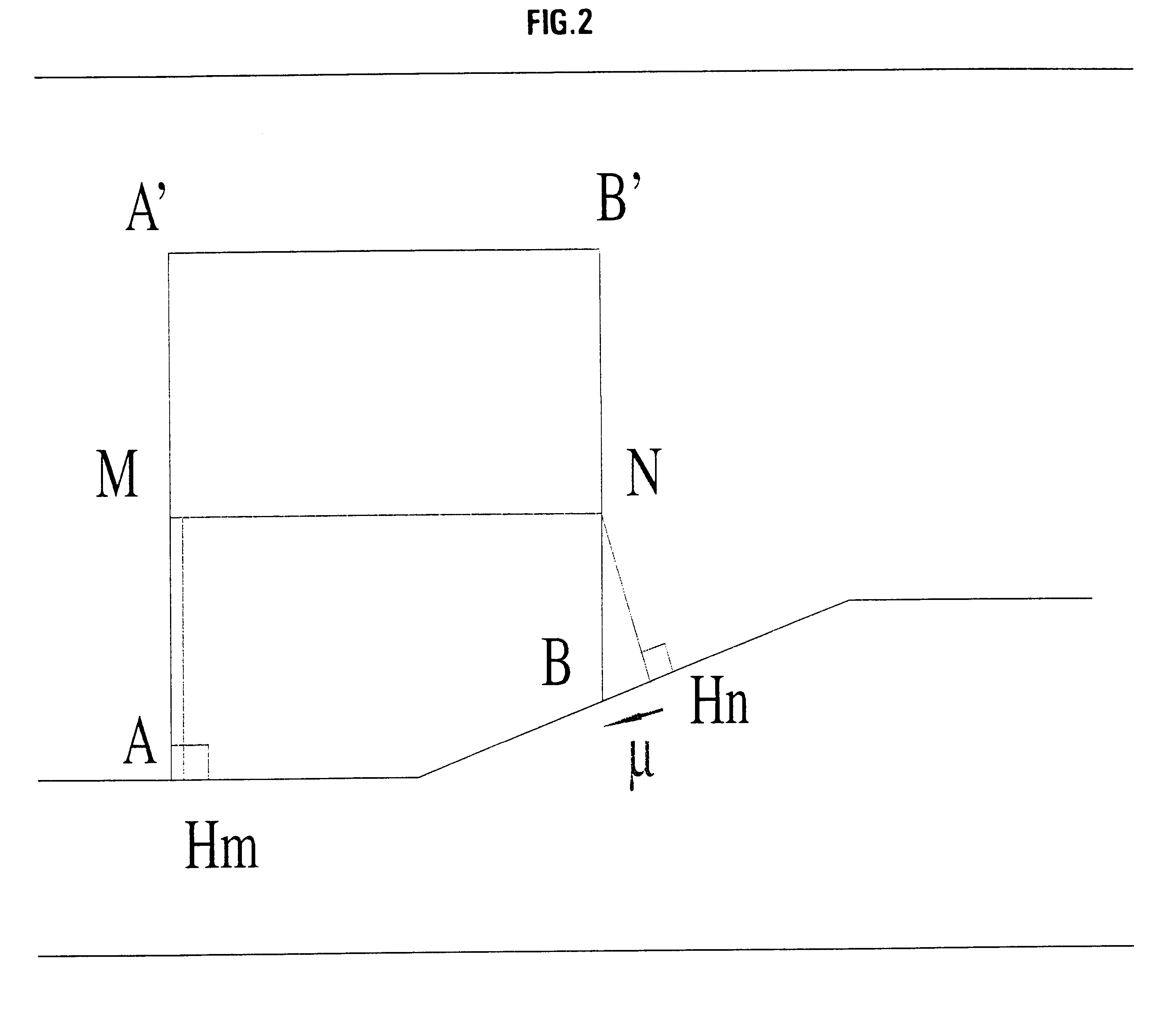
The deformation of a layer of a sedimentary basin can be considered to be globally rigid, the inner deformations being local and situated at the interfaces between the layers or at the slope break points. This deformation by rigid blocks is made possible, on the one hand, by cataclastic processes allowing motion of blocks by fracturation-breaking at the boundary thereof, and on the other hand by a creep phenomenon through dissolution-crystallization under stress. In the latter case, the relative displacements of the blocks are combined with dissolution processes in the zones subjected to the highest stresses (stylolites, cleavage structure) and with precipitation into the empty spaces open between the blocks through deformation (crystal fissures).

To carry out the modeling operation, the zone to be modelled is divided into blocks of greater size (hm-km) that can be readily dealt with by the commonly available calculating devices, considering that the smaller-sca...


PUM


Abstract

A method for forming a prograde kinematic model allowing reproduction in 3D intermediate geometries of geologic objects of an underground zone such as a sedimentary basin, from an initial state to a current state. A representation of the current geometry of the geologic objects of the zone is formed by interpretation of acquired data obtained by seismic exploration, by in-situ measurements and by observations, then each geologic object is subdivided into layers separated by deformation interfaces. Each one of the layers is defined by means of a grid pattern into a series of hexahedral volume elements. Tectonic deformations are then applied separately and successively to each series of volume elements of a layer in relation to an underlying layer while conserving the thickness and the surface area of an intermediate neutral surface in each volume element. Then the tectonic deformations are iteratively modified until a geologic representation substantially in accordance with the known final state of the underground zone is obtained.

Description

The present invention relates to a method for forming a 3D kinematic deformation model of a sedimentary basin from an initial non-deformed state.DESCRIPTION OF THE PRIOR ARTMechanical 3D models of sedimentary basin deformations have already been made. However, these models lead to very complex formulations that have substantial calculating time. An example of such a modeling method is for example described by:Scott M. et al (1991) <<Geometrical Modeling of Fault-related Folds: a Pseudo-three-dimensional Approach>>; Journal of Structural Geology, 13, pp.801-812.Among the existing kinematic models of sedimentary basins, the following models working in 2D can for example be mentioned, described by:Suppe J. <<Geometry and Kinematic of Fault-bent Folding>>, Am. Journal of Science, 283, pp.684-721 (1993), which does not deal with mechanical compaction, andWaltham D. <<Finite Difference Modeling of Sandbox Analogues, Compaction and Detachment Free Deformation&...

Claims


Application Information

Patent Timeline
IPC IPC(8): G01V11/00
CPCG01V11/00
Inventor CORNU, TRISTANSCHNEIDER, FREDERIC
Owner INST FR DU PETROLE
Why Eureka
Try Eureka