Hybrid structural-geometric technique for performing draping simulation of woven fabric composites

a technology of woven fabric and hybrid structure, applied in the field of computer-aided design, can solve the problems of large computational overhead, high cost of composite materials, and high cost of composite materials, and achieve the effects of significant computational overhead, hybrid approach, and simple representation

Active Publication Date: 2021-07-20
AUTODESK INC
View PDF9 Cites 0 Cited by
  • Summary
  • Abstract
  • Description
  • Claims
  • Application Information

AI Technical Summary

Benefits of technology

[0007]At least one advantage of the disclosed techniques is that they employ a hybrid approach that combines geometric information related to the topology of the 3D surface with a simple representation of the fabric's structural characteristics to perform a draping simulation of the fabric over a 3D surface. As a result, the hybrid approach can be more accurate than a conventional geometric approach that uses only geometric topology to drape a 2D fabric over a 3D surface and can executed faster than a conventional FE approach that involves significant computational overhead before converging on a solution that satisfies a large number of boundary conditions. Thus, the hybrid approach provides technological improvements in the execution, efficiency, and / or accuracy of draping simulations of fabrics performed by computer systems or computer-aided design applications relative to prior art approaches.

Problems solved by technology

On the other hand, composite materials are typically associated with higher fabrication costs than metals.
Existing approaches for simulating the draping of composite fabrics typically involve a tradeoff between speed and accuracy.
Accordingly, the geometric approach typically executes efficiently but can be somewhat inaccurate, while the FE approach typically requires significant computational overhead but can converge accurately on a solution that satisfies all boundary conditions.

Method used


Image

  • Hybrid structural-geometric technique for performing draping simulation of woven fabric composites
  • Hybrid structural-geometric technique for performing draping simulation of woven fabric composites
  • Hybrid structural-geometric technique for performing draping simulation of woven fabric composites

Examples


Embodiment Construction

[0017]In the following description, numerous specific details are set forth to provide a more thorough understanding of the various embodiments. However, it will be apparent to one of skilled in the art that the inventive concepts may be practiced without one or more of these specific details.

System Overview

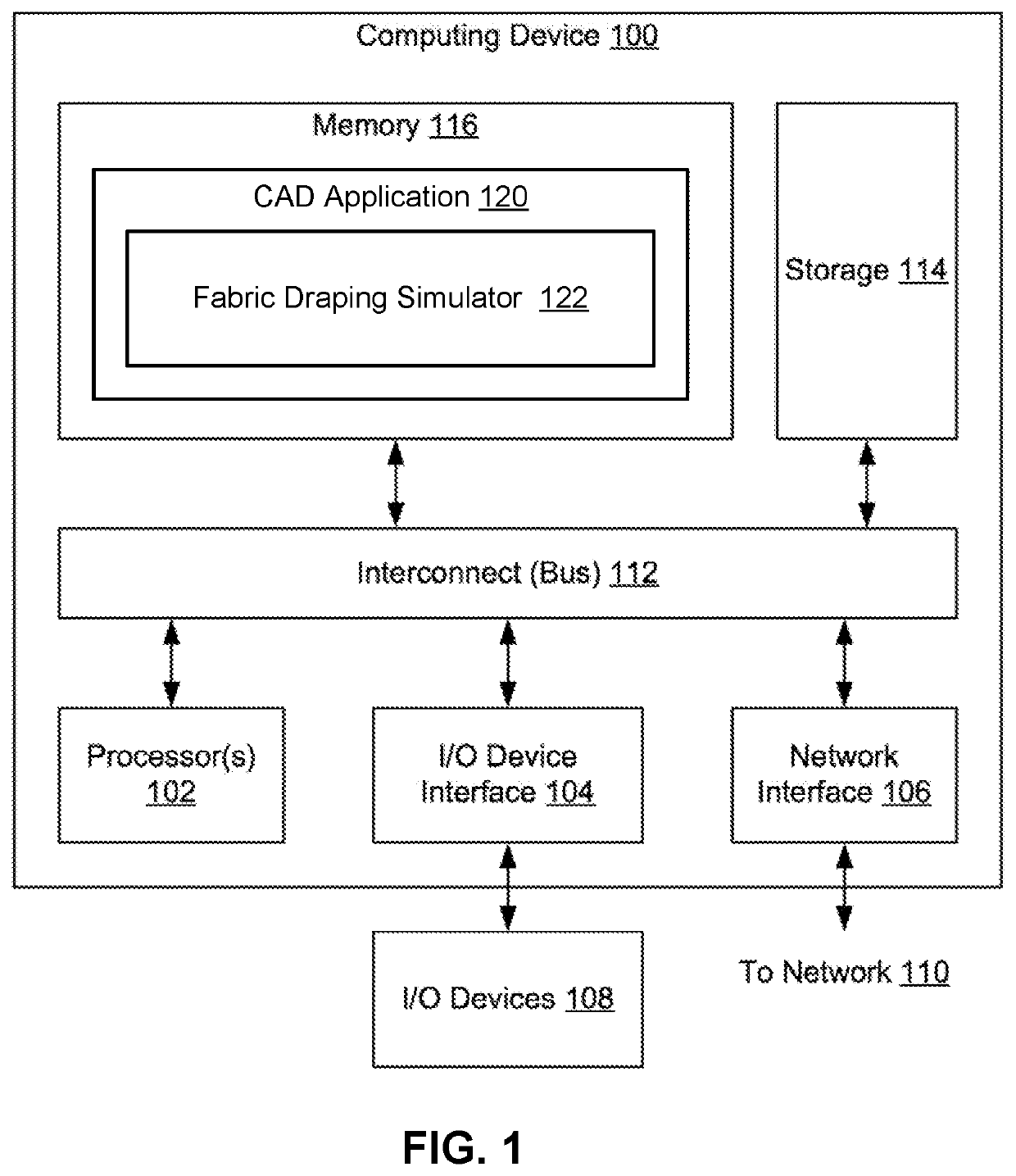
[0018]FIG. 1 illustrates a computing device 100 configured to implement one or more aspects of the present invention. Computing device 100 may be a desktop computer, a laptop computer, a smart phone, a personal digital assistant (PDA), tablet computer, or any other type of computing device configured to receive input, process data, and optionally display images, and is suitable for practicing one or more embodiments of the present invention. Computing device 100 is configured to run productive congestion application 150 that resides in a memory 116. In some embodiments, computing device 100 is also configured to run space design application 118. It is noted that the computing dev...


PUM

PropertyMeasurementUnit
fabric cell sizeaaaaaaaaaa
cell sizeaaaaaaaaaa
resistanceaaaaaaaaaa

Abstract

One embodiment of the present invention sets forth a technique for performing a draping simulation of a fabric that includes obtaining a problem definition that includes a fabric cell size, a spring constant ratio, and a three-dimensional (3D) surface. The technique also includes representing the fabric as a set of fabric cells with dimensions that adhere to the fabric cell size, modeling the fabric cells based on a set of side springs and a set of diagonal springs, and setting a first spring constant of the side springs and a second spring constant of the diagonal springs based on the spring constant ratio. The technique further includes propagating the fabric cells along the 3D surface according to the fabric cell size, the first spring constant, and the second spring constant to generate a result of the draping simulation.

Description

CROSS-REFERENCE TO RELATED APPLICATIONS[0001]This application claims the benefit of United States provisional patent application titled, “TECHNIQUES FOR PERFORMING DRAPING SIMULATIONS OF WOVEN FABRIC COMPOSITES,” filed on Feb. 21, 2018 and having Ser. No. 62 / 633,550. The subject matter of this related application is hereby incorporated herein by reference.BACKGROUND OF THE INVENTIONField of the Invention[0002]Embodiments of the present invention relate generally to computer-aided design, and more PARTICULARLY, to a hybrid structural-geometric technique for performing draping simulation of woven fabric composites.Description of the Related Art[0003]Advancements in automation and manufacturing techniques have increased the use of composite materials, also known as composite fabrics or composite textiles, in automotive, aerospace, marine, construction, and other industries. Such materials have a high strength to weight ratio, formability, and impact and corrosion resistance compared to...

Claims


Application Information

Patent Timeline
Patent Type & Authority Patents(United States)
IPC IPC(8): G06T15/00
CPCG06T15/005G06T19/00G06T2210/16G06F30/20G06F2113/12G06F2113/26
Inventor EBRAHIMI, MEHRANMORUZZI, MASSIMILIANOIORIO, FRANCESCO
Owner AUTODESK INC
Why Eureka
Try Eureka