Multi-Level Product Display Device

a product display and multi-level technology, applied in the direction of scaffold accessories, washstands, light support devices, etc., can solve the problems of not maximizing product density and presenting bags, and achieve the effect of increasing product exposure, maximizing product density, and improving the shopping experience for consumers

Inactive Publication Date: 2010-06-24
HALLMARK CARDS INC
View PDF43 Cites 11 Cited by
  • Summary
  • Abstract
  • Description
  • Claims
  • Application Information

AI Technical Summary

Benefits of technology

[0006]The present invention provides a universal merchandise display device capable of displaying a plurality of unique products of various sizes in one merchandisable location to maximize product density and improve the shopping experience for consumers and retailers. The device uses a plurality of elements or hooks of varying lengths that are arrayed to present product as a collection or a system of complimentary product components, such as a bags with bows, ribbons and other accessories. The elements, which could also be referred to as product hangers, have defined product hanging locat

Problems solved by technology

Conventional methods of gift bag merchandising often used in retail environments fail to maximize product density and

Method used


Image

  • Multi-Level Product Display Device
  • Multi-Level Product Display Device
  • Multi-Level Product Display Device

Examples


first embodiment

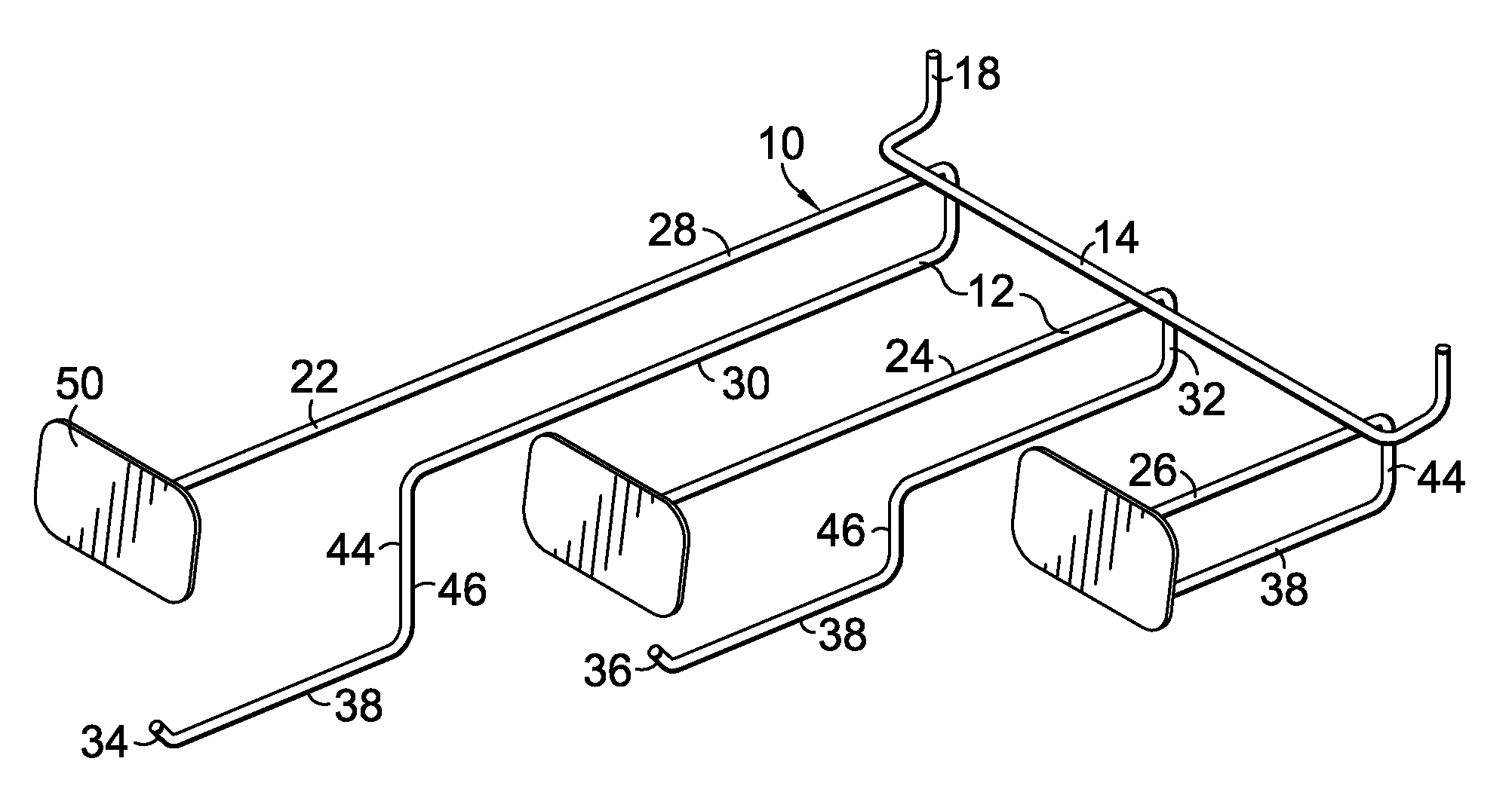
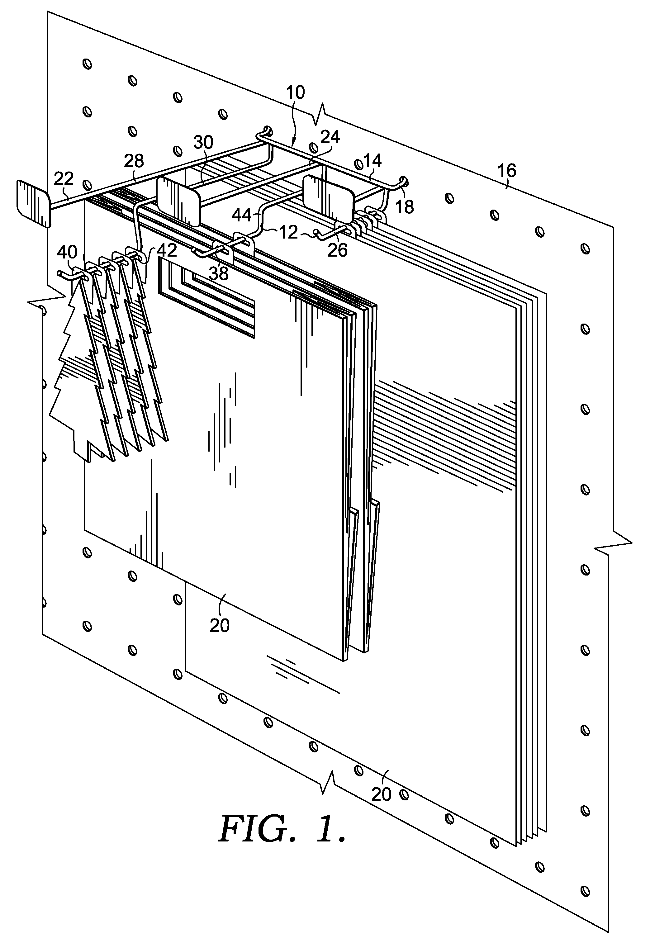
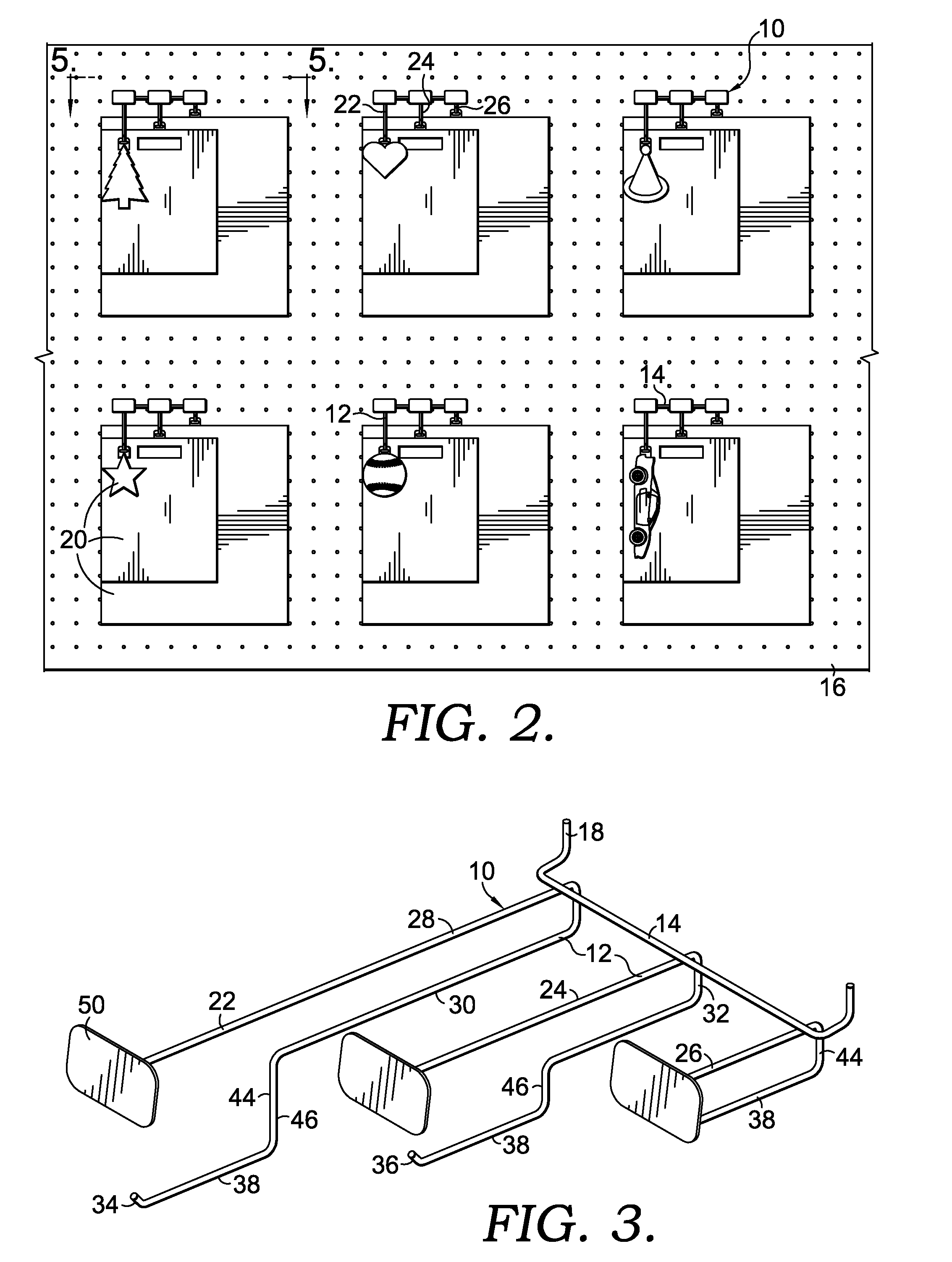
[0020]FIGS. 1-5 illustrate the display device 10. In this illustrated embodiment, the display device 10 has three elements 12, which will be referenced as a first element 22, a second element 24 and a third element 26. The elements 12 are generally sideways, U-shaped components that have an upper prong 28 and a lower prong 30. The elements 12, as well as the connecting member 14 and the attachment means 18, are all preferably formed from metal wire or rod stock which has been bent into the desired and illustrated orientation and welded together. It should be readily understood, however, by one of ordinary skill in the art, that the display device 10 could be formed of material other than metal (e.g., plastic, wood, etc.) and from other than bent wire (e.g., molded or preformed parts).

[0021]The lower prongs 30 have a proximal end 32 and a distal end 34. To prevent product 20 from accidentally sliding off of the lower prong 30, the lower prong 30 is preferably provided with an upwardl...

second embodiment

[0027]FIGS. 6 and 7 illustrate a display device 10 of the present invention. In this embodiment, the hanging locations 38 are still spaced from one another both laterally and longitudinally, as well as horizontally (FIG. 7). In this embodiment, the elements 12 do not include the upper prongs 28 and, while the front of the hanging locations 38 are still defined by the upwardly cantered end portions 36, the rear of the hanging locations 38 are defined by a horizontal stop portion 60.

[0028]The second element 24 does not depend directly from the connecting member 14, but instead is directly coupled to the lower prong 30 of the first element 22. Also, a different attachment means 18 is provided. In that regard, the attachment means 18 takes the form of an upside down U-shaped channel 62 that provides for the display device 10 to be coupled with a display fixture (not shown) by placing the channel 62 over a horizontal bracket (not shown) of the display fixture.

[0029]FIG. 8 illustrates a t...

third embodiment

[0030]The connecting member 14 of the third embodiment includes a plurality of notches 64 across an upper periphery 66 thereof. A pair of flanges 68 extend rearwardly from the connecting member 14 and include a plurality of aligned apertures 70 therethrough. Proximate ends 32 of the lower prongs 30 are turned vertically downward and are received in the apertures 70 to connect the elements 12 to the connecting member 14. A portion of the lower prongs 30 is then received in a notch 64 to prevent lateral movement. This arrangement permits lateral adjustment or spacing of the elements 12 to control the distance between the elements 12 to accommodate product 20 of varying sizes. The attachment means 18 takes the form of a horizontal C-shaped channel 72 that receives an edge of a portion of a display fixture, such as a shelf.


PUM


Abstract

A display device for presenting product in a hanging orientation includes a plurality of hanging locations spaced apart from each other both laterally and longitudinally. The longitudinal spacing of the hanging locations provides for a layered display of product, while the lateral spacing of the hanging locations provides for the arrangement of products of varying sizes. In some embodiments, the hanging locations are also spaced apart from each other vertically. The vertical spacing of the hanging locations provides for a cascading display of product. The display device is designed to be coupled to and supported by a display fixture.

Description

CROSS-REFERENCE TO RELATED APPLICATIONS[0001]Not applicable.STATEMENT REGARDING FEDERALLY SPONSORED RESEARCH OR DEVELOPMENT[0002]Not applicable.BRIEF SUMMARY OF THE INVENTION[0003]The present invention relates to a display device. More particularly, this invention relates to a device for displaying product for sale in a retail environment in a hanging orientation and a layered arrangement. The device is intended to be coupled with a display fixture and may be of the type that cooperates with a peg board of a fixture.[0004]In retail environments, product is often displayed in a hanging orientation. Prior art displays provide for the use of product hangers that are spaced apart from one another depending on the size of the product being displayed. The number of products that can be displayed, however, is generally based on a factor of their size and the linear footage or square footage area available for product of a particular type. Related items are often, at best, displayed in clos...

Claims


Application Information

Patent Timeline
IPC IPC(8): A47B96/06
CPCA47F5/0823A47F5/0807
Inventor LANGLEY, ROBERT EUGENEPLATKO, APHRODITE HARITOU
Owner HALLMARK CARDS INC
Why Eureka
Try Eureka