Welding and plasma cutting method and system

a plasma cutting and welding technology, applied in the field of electric torches, can solve the problems of increasing costs, reducing the efficiency of various procedures involving the use of different systems, and purchasing or leasing separate standalone units at a significant cos

Inactive Publication Date: 2008-06-26
ILLINOIS TOOL WORKS INC
View PDF37 Cites 84 Cited by
  • Summary
  • Abstract
  • Description
  • Claims
  • Application Information

AI Technical Summary

Problems solved by technology

As a result, these systems must be purchased or leased as separate standalone units at a significant cost.
All of these factors increase costs and reduce efficiency of various procedures involving use of the different systems.

Method used


Image

  • Welding and plasma cutting method and system
  • Welding and plasma cutting method and system
  • Welding and plasma cutting method and system

Examples


Embodiment Construction

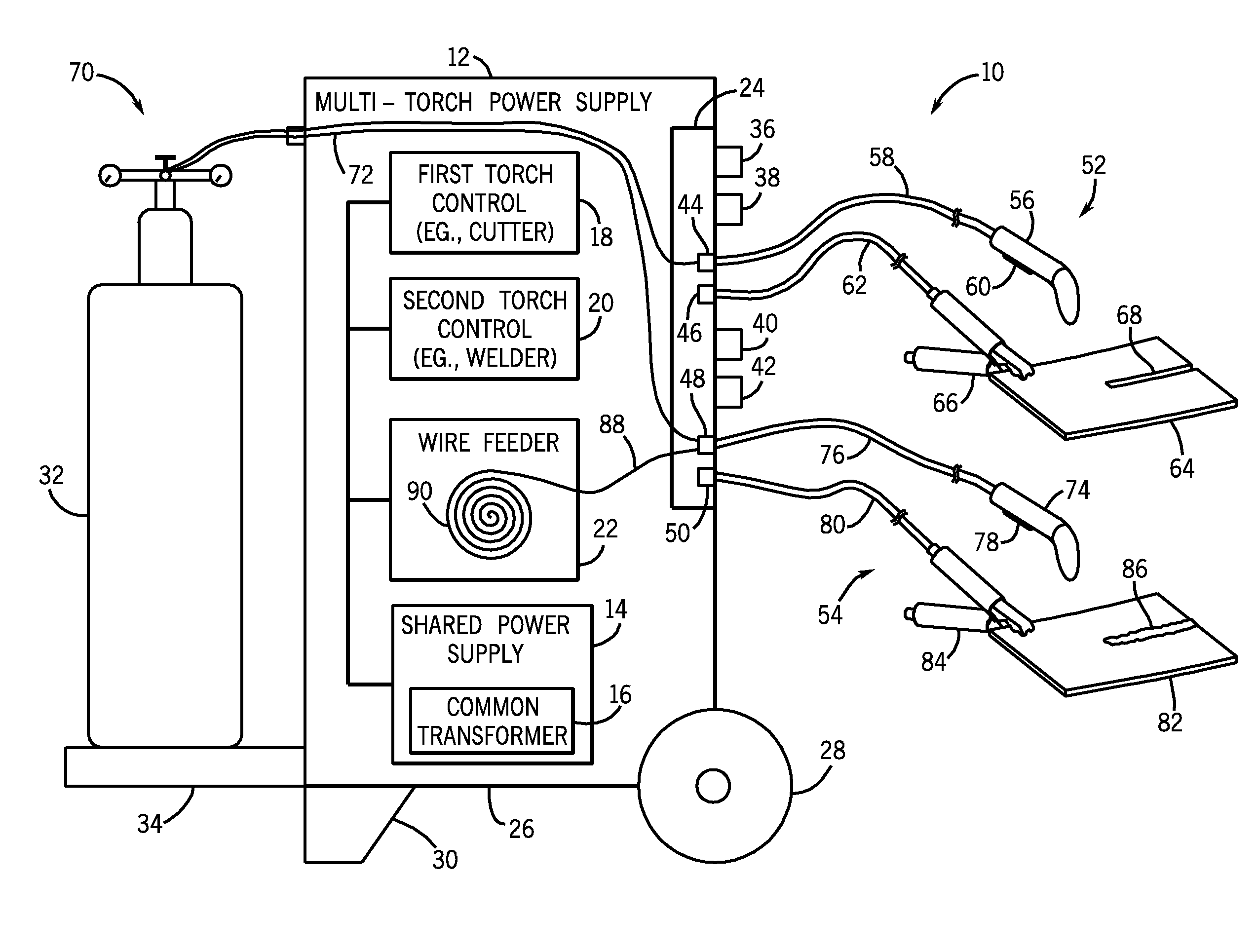
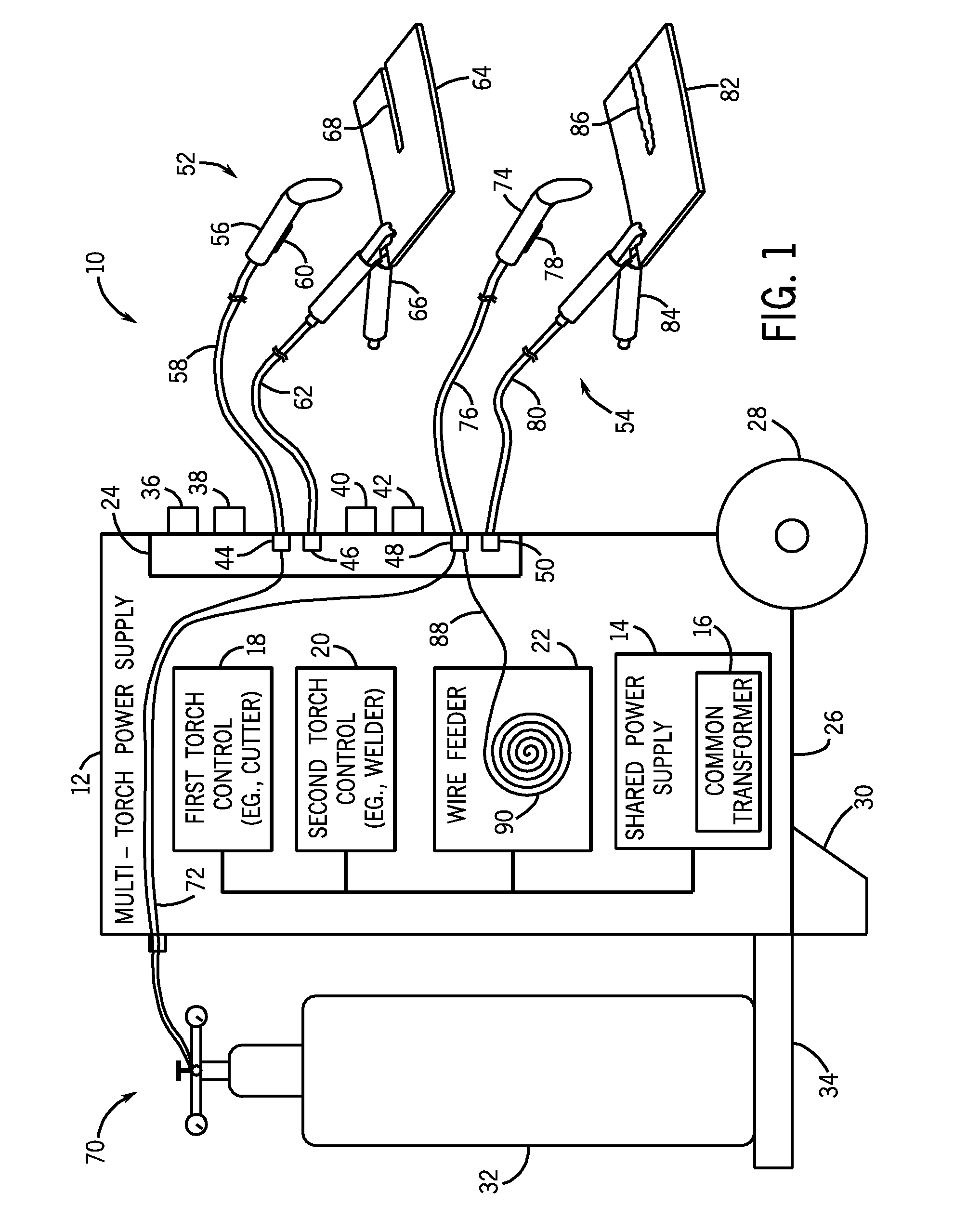
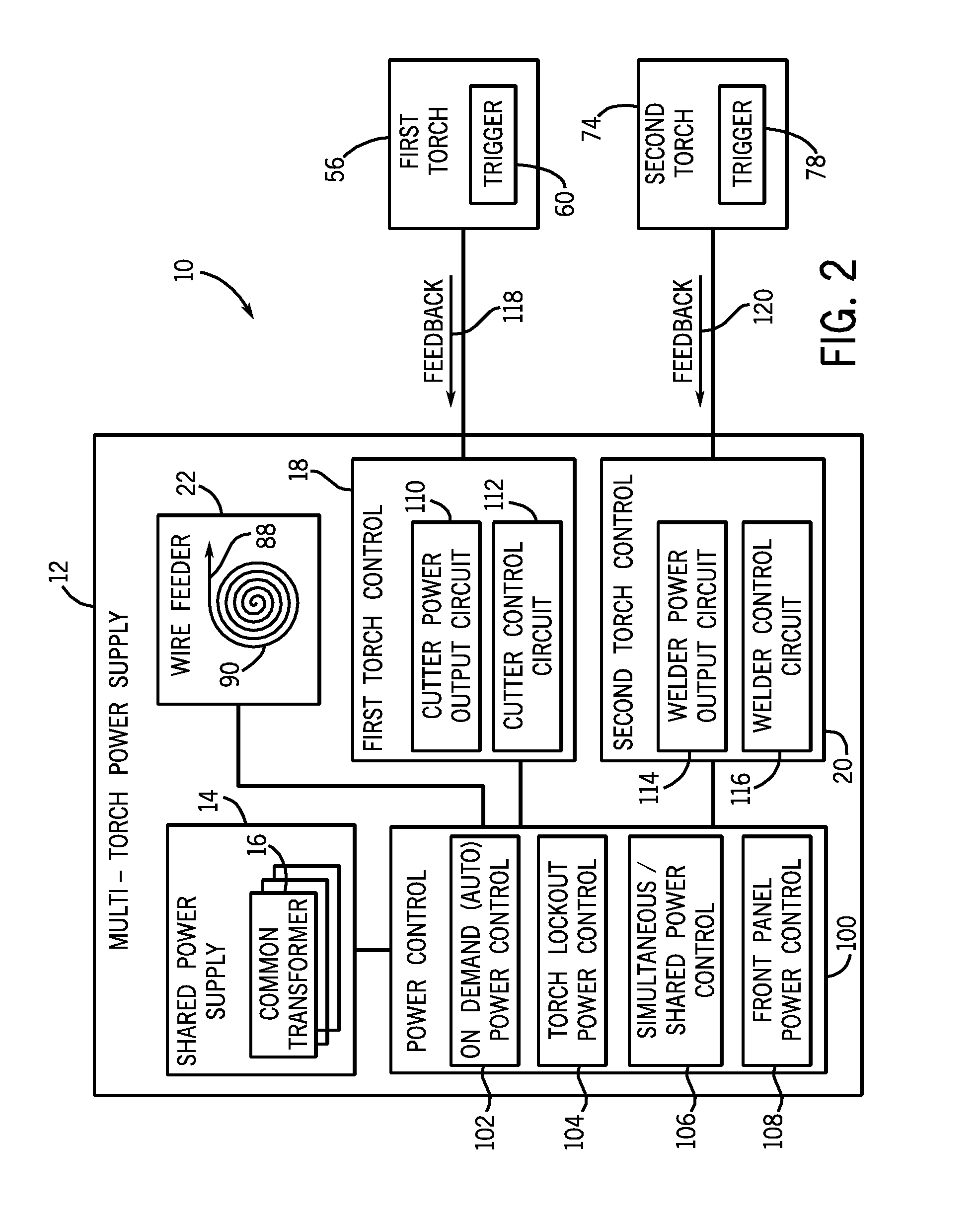
[0010]As discussed in detail below, various torch systems are integrated together in a single chassis using a single power supply, thereby reducing costs, weight, and space consumption of the torch systems. For example, welding torches, cutting torches, or other torches may all be coupled to the single power supply, wherein each torch can receive power on-demand in response to a signal from the torch (e.g., a trigger signal). In other words, each torch may be without power (e.g., cold state) until a user wishes to operate the torch, and then the user may engage a trigger on the torch to command the single power supply to automatically transmit power to the torch (e.g., hot state). In some embodiments, the various torches can operate simultaneously using the single power supply. In other embodiments, operation of one torch may lockout operation of the other torch, and vice versa.

[0011]FIG. 1 is a diagram of an exemplary system 10 having a multi-torch power supply 12 in accordance wit...


PUM

PropertyMeasurementUnit
poweraaaaaaaaaa
lockout poweraaaaaaaaaa
control poweraaaaaaaaaa

Abstract

A system, in some embodiments, includes a multi-torch power supply. The power supply has a first circuit configured to control output to a first electrical torch, and a second circuit configured to control output to a second electrical torch. The power supply also has a power source configured to supply power to the first and second circuits to enable both independent and simultaneous operation of the first and second electrical torches.

Description

CROSS-REFERENCE TO RELATED APPLICATION[0001]This application claims priority to provisional application No. 60 / 876,840 filed on Dec. 22, 2006, which is hereby incorporated by reference.BACKGROUND[0002]The invention relates generally to electrical torches, such as arc welding torches and plasma cutting torches.[0003]In general, electrical torches receive power from standalone units, each with an independent power supply and control circuitry. For example, an arc welding system is generally separate and independent from a plasma cutting system. Each system has different power requirements and operational characteristics, which results in a different power supply for the particular type of torch. Some procedures require the use of a variety of different electrical torches, such as an arc welding torch and a plasma cutting torch. As a result, these systems must be purchased or leased as separate standalone units at a significant cost. Furthermore, these systems must be transported, set ...

Claims


Application Information

Patent Timeline
Patent Type & Authority Applications(United States)
IPC IPC(8): B23K9/00
CPCB23K9/1068B23K10/006B23K9/1735
Inventor LENZNER, JEFFWOODWARD, RONALD D.STANZEL, KENNETH A.
Owner ILLINOIS TOOL WORKS INC
Why Eureka
Try Eureka