

Image-formation optical system and imaging system using the same
a technology of optical system and image, applied in the field of image-formation optical system, can solve the problems of difficult to reduce the whole size of the system, the cost of the first lens, and the inability to manufacture the whole system, and achieve the effect of good correction of axial spherical aberration and coma, and balanced sta
- Summary
- Abstract
- Description
- Claims
- Application Information
AI Technical Summary
Benefits of technology
Problems solved by technology
Method used
Image

Examples
example 1
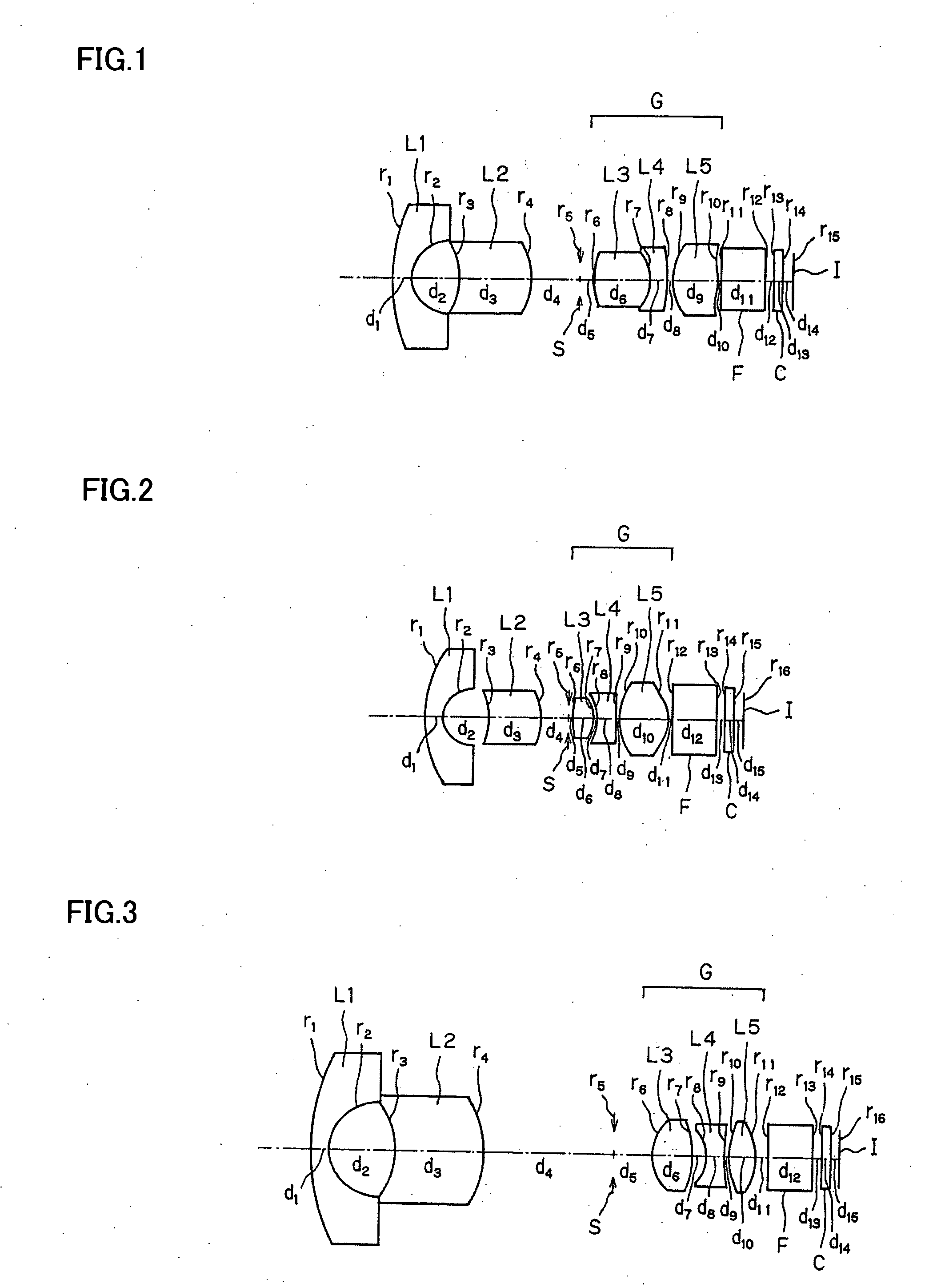
[0080]
r1 = 12.560d1 = 1.00nd1 = 1.88300νd1 = 40.80Y1 = 4.4625r2 = 2.200d2 = 2.77Y2 = 2.1449r3 = −4.464d3 = 4.00nd2 = 1.92286νd2 = 18.90Y3 = 1.9100r4 = −5.057d4 = 2.74Y4 = 2.1486r5 = ∞ (Stop)d5 = 0.82Y5 = 0.9682r6 = 7.864d6 = 3.15nd3 = 1.58313νd3 = 59.38Y6 = 1.2143r7 = −2.860d7 = 1.00nd4 = 1.92286νd4 = 18.90Y7 = 1.5692r8 = −8.963d8 = 0.20Y8 = 1.8531r9 = 4.239d9 = 2.60nd5 = 1.52542νd5 = 55.78Y9 = 2.1000(Aspheric)r10 = −5.934d10 = 0.20Y10 = 1.8739(Aspheric)r11 = ∞d11 = 2.50nd6 = 1.54771νd6 = 62.84Y11 = 1.8676r12 = ∞d12 = 0.50Y12 = 1.8334r13 = ∞d13 = 0.50nd7 = 1.51633νd7 = 64.14Y13 = 1.8230r14 = ∞d14 = 0.50Y14 = 1.8162r15 = ∞Y15 = 1.8059(Image Plane)Aspherical Coefficients9th surfaceK = −2.2388A4 = 4.24507 × 10⁻³A6 = 1.48443 × 10⁻³A8 = −1.29917 × 10⁻⁴A10 = 1.19586 × 10−510th surfaceK = −3.791A4 = 2.57583 × 10⁻³A6 = 4.28150 × 10⁻³A8 = −1.08079 × 10⁻³A10 = 2.25792 × 10⁻⁴
example 2
[0081]
r1 = 8.343d1 = 1.00nd1 = 1.88300νd1 = 40.80Y1 = 4.2718r2 = 1.782d2 = 2.66Y2 = 1.7815r3 = −4.389d3 = 3.00nd2 = 1.92286νd2 = 18.90Y3 = 1.5546r4 = −4.012d4 = 1.50Y4 = 1.6208r5 = ∞ (Stop)d5 = 0.25Y5 = 0.8138r6 = 7.081d6 = 1.20nd3 = 1.54771νd3 = 62.84Y6 = 0.9440r7 = −2.463d7 = 0.20Y7 = 1.1244r8 = −2.538d8 = 1.00nd4 = 1.92286νd4 = 18.90Y8 = 1.1366r9 = −158.015d9 = 0.20Y9 = 1.4700r10 = 3.505d10 = 2.80nd5 = 1.52542νd5 = 55.78Y10 = 1.8927(Aspheric)r11 = −2.393d11 = 0.20Y11 = 2.0629(Aspheric)r12 = ∞d12 = 2.50nd6 = 1.54771νd6 = 62.84Y12 = 2.0005r13 = ∞d13 = 0.50Y13 = 1.8929r14 = ∞d14 = 0.50nd7 = 1.51633νd7 = 64.14Y14 = 1.8602r15 = ∞d15 = 0.50Y15 = 1.8387r16 = ∞Y16 = 1.8060(Image Plane)Aspherical Coefficients10th surfaceK = −4.6170A4 = −9.49294 × 10⁻⁴A6 = 1.14267 × 10⁻³A8 = 1.56300 × 10⁻⁴A10 = −2.55739 × 10−511th surfaceK = −0.7362A4 = 5.97480 × 10⁻³A6 = 7.06325 × 10⁻⁴A8 = −1.70964 × 10⁻⁴A10 = 5.45160 × 10⁻⁵
example 3
[0082]
r1 = 14.652d1 = 1.00nd1 = 1.83400νd1 = 37.20Y1 = 6.0412r2 = 2.945d2 = 3.84Y2 = 2.9168r3 = −4.900d3 = 5.00nd2 = 1.84666νd2 = 23.80Y3 = 2.7085r4 = −7.200d4 = 7.29Y4 = 3.2825r5 = ∞ (Stop)d5 = 2.16Y5 = 1.3533r6 = 3.023d6 = 2.41nd3 = 1.54771νd3 = 62.84Y6 = 2.0833r7 = −5.915d7 = 0.75Y7 = 1.8842r8 = −2.749d8 = 1.00nd4 = 1.84666νd4 = 23.80Y8 = 1.6322r9 = 23.874d9 = 0.20Y9 = 1.8525r10 = 3.881d10 = 1.55nd5 = 1.52542νd5 = 55.78Y10 = 2.0335(Aspheric)r11 = −4.097d11 = 0.73Y11 = 2.1000(Aspheric)r12 = ∞d12 = 2.50nd6 = 1.54771νd6 = 62.84Y12 = 2.0194r13 = ∞d13 = 0.50Y13 = 1.9165r14 = ∞d14 = 0.50nd7 = 1.51633νd7 = 64.14Y14 = 1.8852r15 = ∞d15 = 0.50Y15 = 1.8646r16 = ∞Y16 = 1.8401(Image Plane)Aspherical Coefficients10th surfaceK = −11.6715A4 = 1.31766 × 10⁻²A6 = −3.56204 × 10⁻³A8 = 1.56300 × 10⁻⁴A10 = 3.28622 × 10−411th surfaceK = 0.8832A4 = 1.42340 × 10⁻³A6 = 1.80518 × 10⁻³A8 = −4.80072 × 10⁻⁴A10 = 4.08437 × 10⁻⁵
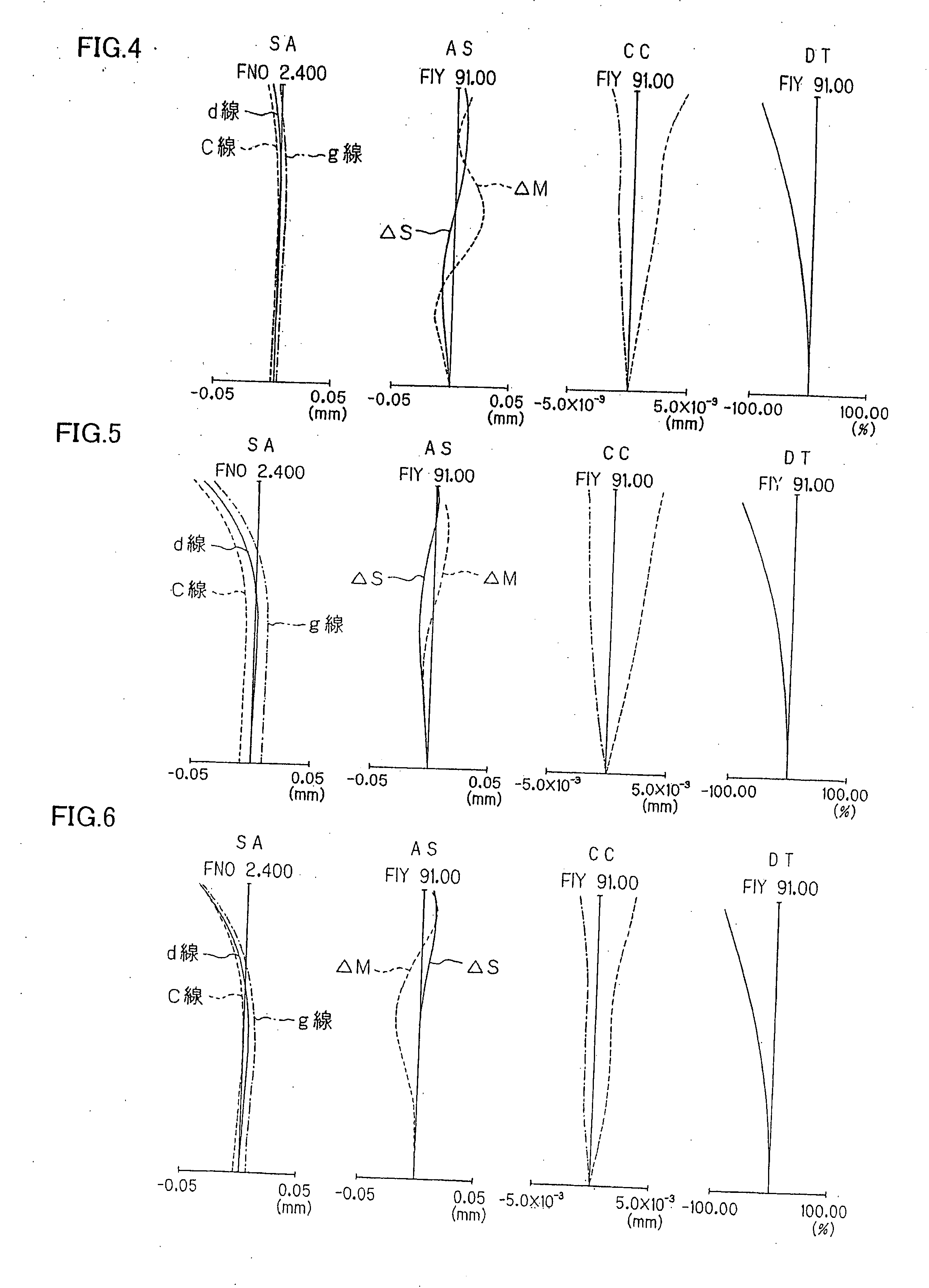
[0083]FIGS. 4, 5 and 6 are aberration diagrams for Examples 1, 2, and 3, respectivel...
PUM
 Abstract
Description
Claims
Application Information