Motor Vehicle and Control Method of Motor Vehicle

Inactive Publication Date: 2008-06-26
TOYOTA JIDOSHA KK
View PDF11 Cites 55 Cited by
  • Summary
  • Abstract
  • Description
  • Claims
  • Application Information

AI Technical Summary

Benefits of technology

[0041]When the measured vehicle speed is not higher than the preset reference vehicle speed and when the detected road gradient is not less than the preset reference gradient, the third control method of a motor vehicle of the invention sets the target driving force for constant-speed driving of the motor vehicle at the target vehicle speed, which is set to be not higher than the preset reference vehicle speed, based on the road gradient. When the driving force demand in response to the driver's operation is not less than the target driving force, the operation of the internal combustion engine is controlled to output the driving force demand. When the driving force demand is less than the target driving force, the operation of the internal combustion engine is controlled to output th

Problems solved by technology

This prior art motor vehicle does not perform the feedback control of the intake air flow to attain the target creep vehicle speed in an accelerator-on position or in a brake-on position.
When the driver's depression amount of an accelerator pedal or a brake pedal is insufficient against a certain road gradient, this mot

Method used


Image

  • Motor Vehicle and Control Method of Motor Vehicle
  • Motor Vehicle and Control Method of Motor Vehicle
  • Motor Vehicle and Control Method of Motor Vehicle

Examples


first embodiment

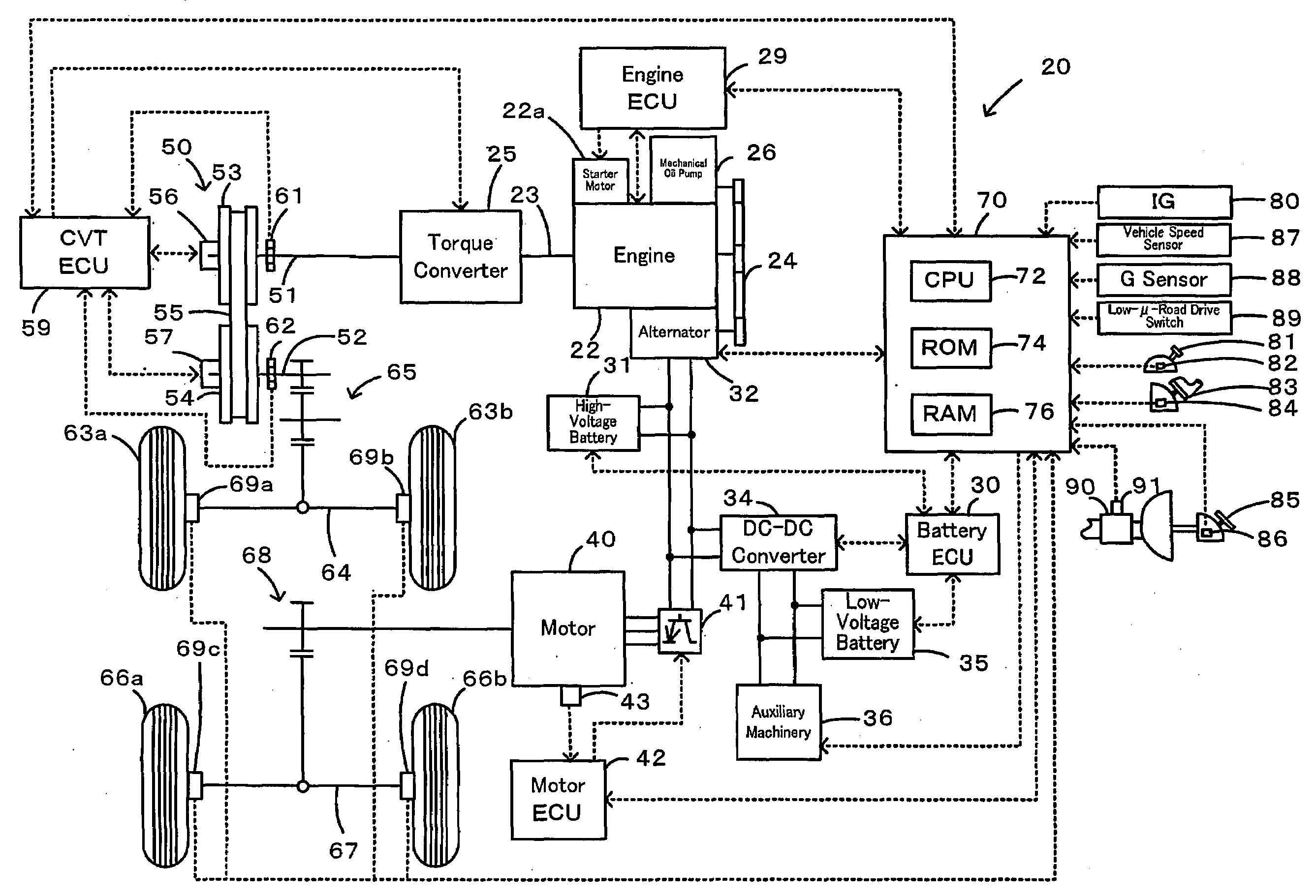
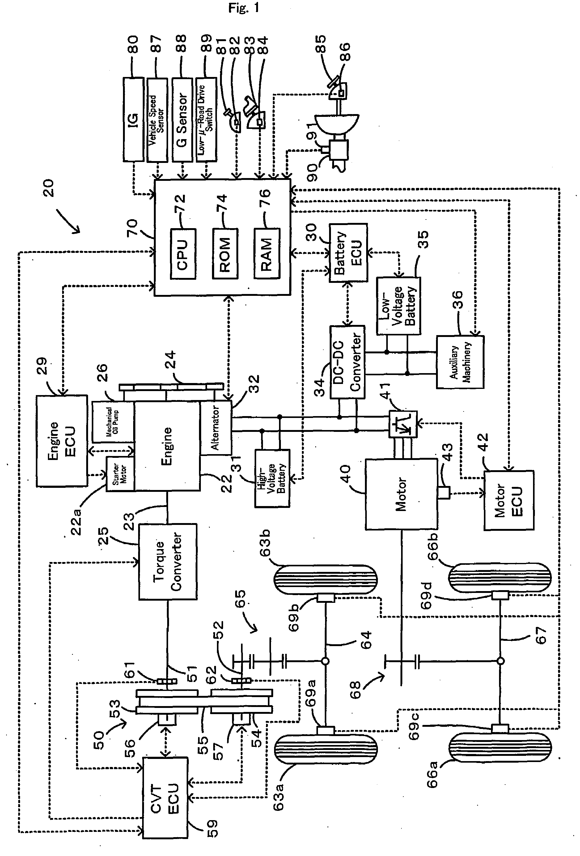
[0060]Some modes of carrying out the invention are discussed below as preferred embodiments with reference to the accompanied drawings. FIG. 1 schematically illustrates the configuration of a hybrid vehicle 20 in one embodiment of the invention. The hybrid vehicle 20 of the embodiment is a four-wheel drive vehicle and has a front-wheel drive system of transmitting the output power of an engine 22 to a front axle 64 via a torque converter 25, a continuously variable transmission (CVT) 50, and a gear mechanism 65 to drive front wheels 63a and 63b, a rear wheel drive system of transmitting the output power of a motor 40 to a rear axle 67 via a gear mechanism 68 to drive rear wheels 66a and 66b, and a hybrid electronic control unit 70 of controlling the operations of the whole hybrid vehicle 20.

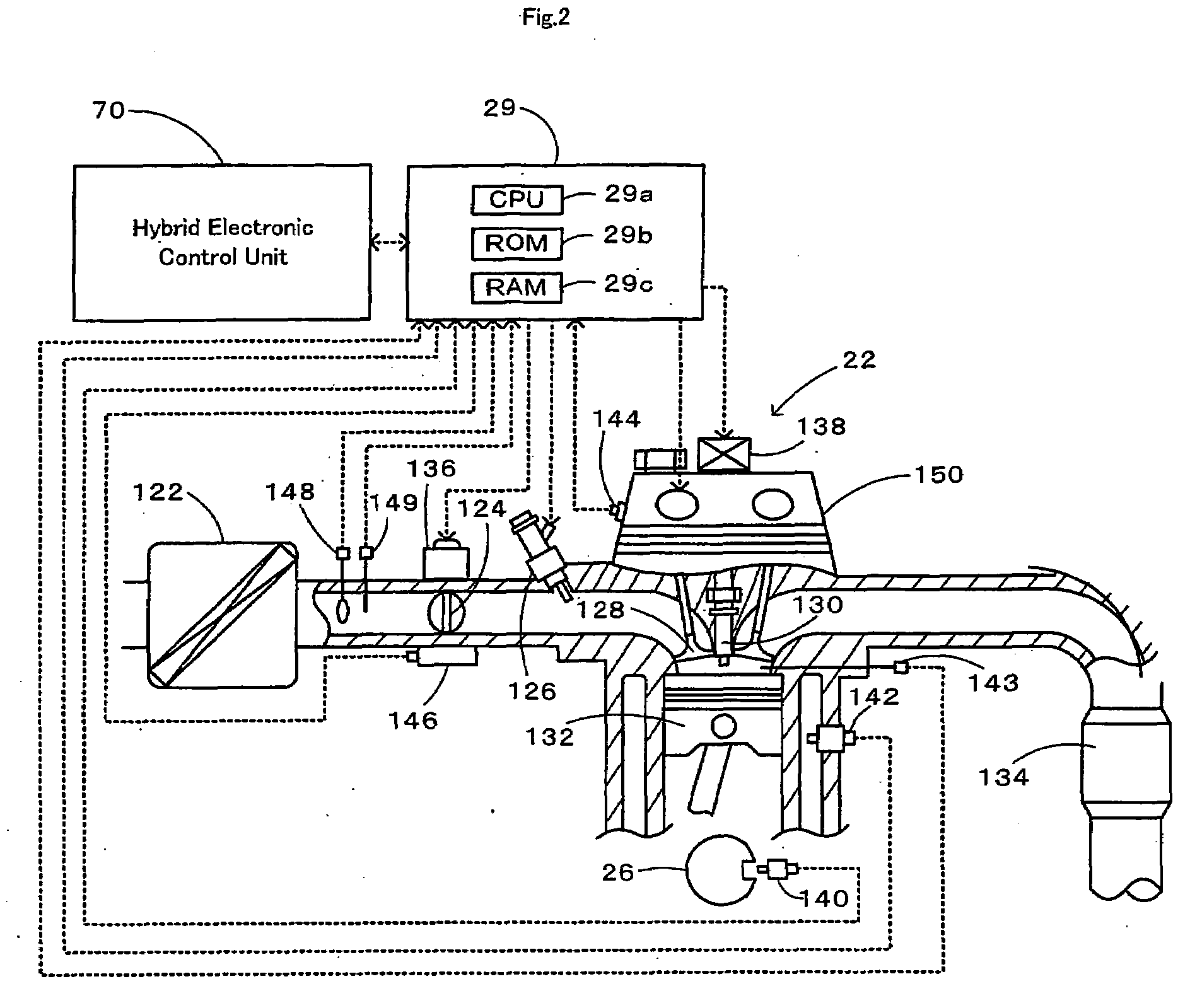
[0061]The engine 22 is an internal combustion engine that consumes a hydrocarbon fuel, such as gasoline or light oil, to output power. As shown in FIG. 2, the air cleaned by an air cleaner 122 an...

second embodiment

[0083]A hybrid vehicle 20B is described below as a second embodiment of the invention. The hardware configuration of the hybrid vehicle 20B of the second embodiment is identical with that of the hybrid vehicle 20 of the first embodiment and is thus not specifically described here. The hardware elements in the hybrid vehicle 20B of the second embodiment are expressed by the same numerals and symbols as those allocated to the hardware elements in the hybrid vehicle 20 of the first embodiment.

[0084]The hybrid vehicle 20B of the second embodiment executes a low-speed hill drive control routine of FIG. 11, instead of the low-speed hill drive control routine of FIG. 3. The low-speed hill drive control routine of FIG. 11 is similar to the low-speed hill drive control routine of FIG. 3 with some modifications. The modifications include replacement of step S100 with step S100B and addition of some steps, prior to step S110 where the gradient-corresponding rotation speed Nθ is set as the rota...


PUM


Abstract

During a starting operation or a low-speed drive of a vehicle on a slope, the drive control of the invention sets a gradient-corresponding rotation speed N? as a rotation speed of an engine to output a required driving force against a longitudinal vehicle gradient ?fr (step S110), and sequentially sets a low-?-road correction rotation speed Nlow upon identification of a low-?-road drive condition, a vehicle speed difference-compensating rotation speed Nv based on a vehicle speed V, and a brake-based correction rotation speed Nb based on a brake pressure Pb (steps S120 through S250). The drive control sets a target engine rotation speed Ne* based on these settings (step S260) and subsequently sets a target throttle opening THtag (step S270). The operation of the engine is controlled with the greater between the target throttle opening THtag and a required throttle opening THreq corresponding to an accelerator opening Acc (step S290). This arrangement effectively prevents an unexpected slide-down of the vehicle along the slope.

Description

TECHNICAL FIELD[0001]The present invention relates to a motor vehicle and its control method.BACKGROUND ART[0002]One proposed technique applied to a motor vehicle feedback controls the intake air flow of an internal combustion engine for output of a driving power to set the idling state in a drivable gearshift position and to attain a target creep vehicle speed under the condition of both an accelerator-off position and a brake-off position (see, for example, Japanese Patent Laid-Open Gazette No. H10-166897). This prior art motor vehicle is supposed not to slide down along a slope under the brake-off condition on a hill start.DISCLOSURE OF THE INVENTION[0003]This prior art motor vehicle does not perform the feedback control of the intake air flow to attain the target creep vehicle speed in an accelerator-on position or in a brake-on position. When the driver's depression amount of an accelerator pedal or a brake pedal is insufficient against a certain road gradient, this motor vehic...

Claims


Application Information

Patent Timeline
IPC IPC(8): B60K31/00B60K6/44B60K6/52B60K6/543B60W10/04B60W10/06B60W10/08B60W10/18B60W10/184B60W20/00B60W30/00F02D29/02
CPCB60K6/44Y10T477/676B60W10/184B60W20/00B60W30/18027B60W30/18118B60W2510/182B60W2520/10B60W2520/26B60W2550/142B60W2550/147B60W2550/148F02D31/003F02D41/021Y02T10/623Y10T477/735Y10T477/75Y10T477/747Y10T477/6433B60W10/06B60L3/0076B60L3/106B60L7/14B60L15/20B60L15/2018B60L2240/12B60L2240/421B60L2240/423B60L2240/441B60L2240/443B60L2240/465B60L2260/26B60L2260/28B60L15/2081Y02T10/70Y02T10/72B60L50/16B60L58/20B60W2552/35B60W2552/40B60W2552/15Y02T10/62Y02T10/64Y02T10/7072F02D31/00F02D35/00B60W10/04B60W20/12
Inventor OKUDA, KOICHITABATA, MITSUHIROSATO, HIROSHI
Owner TOYOTA JIDOSHA KK
Why Eureka
Try Eureka