
Graph-theoretic technique of analyzing and optimizing policy deployment

a graph-theoretic technique and policy deployment technology, applied in the field of policy management, can solve the problems of changing business needs and environmental conditions, changing the order of application of policies and their use in unexpected ways, and at least four important limitations

Inactive Publication Date: 2008-07-03
MOTOROLA INC
View PDF4 Cites 39 Cited by
  • Summary
  • Abstract
  • Description
  • Claims
  • Application Information

AI Technical Summary

Benefits of technology

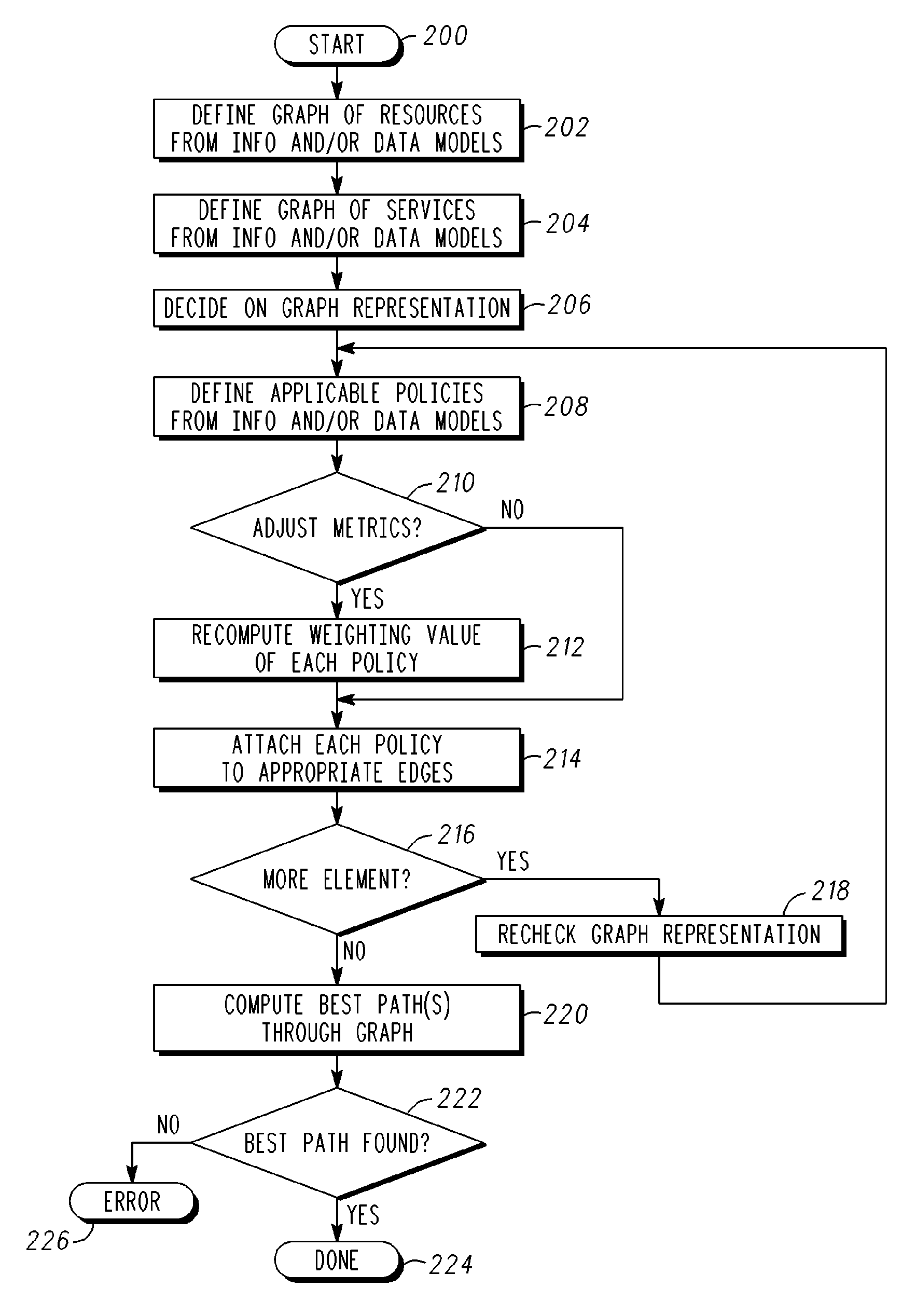
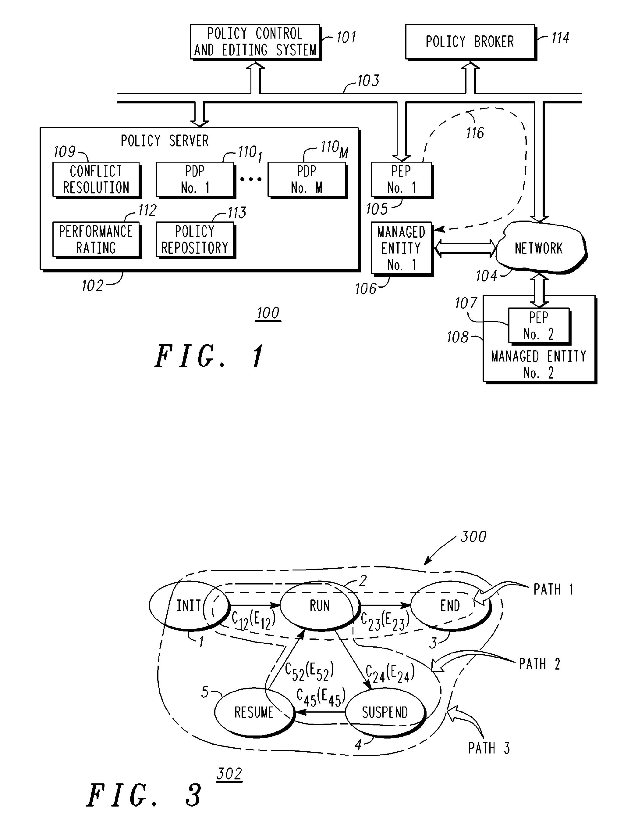
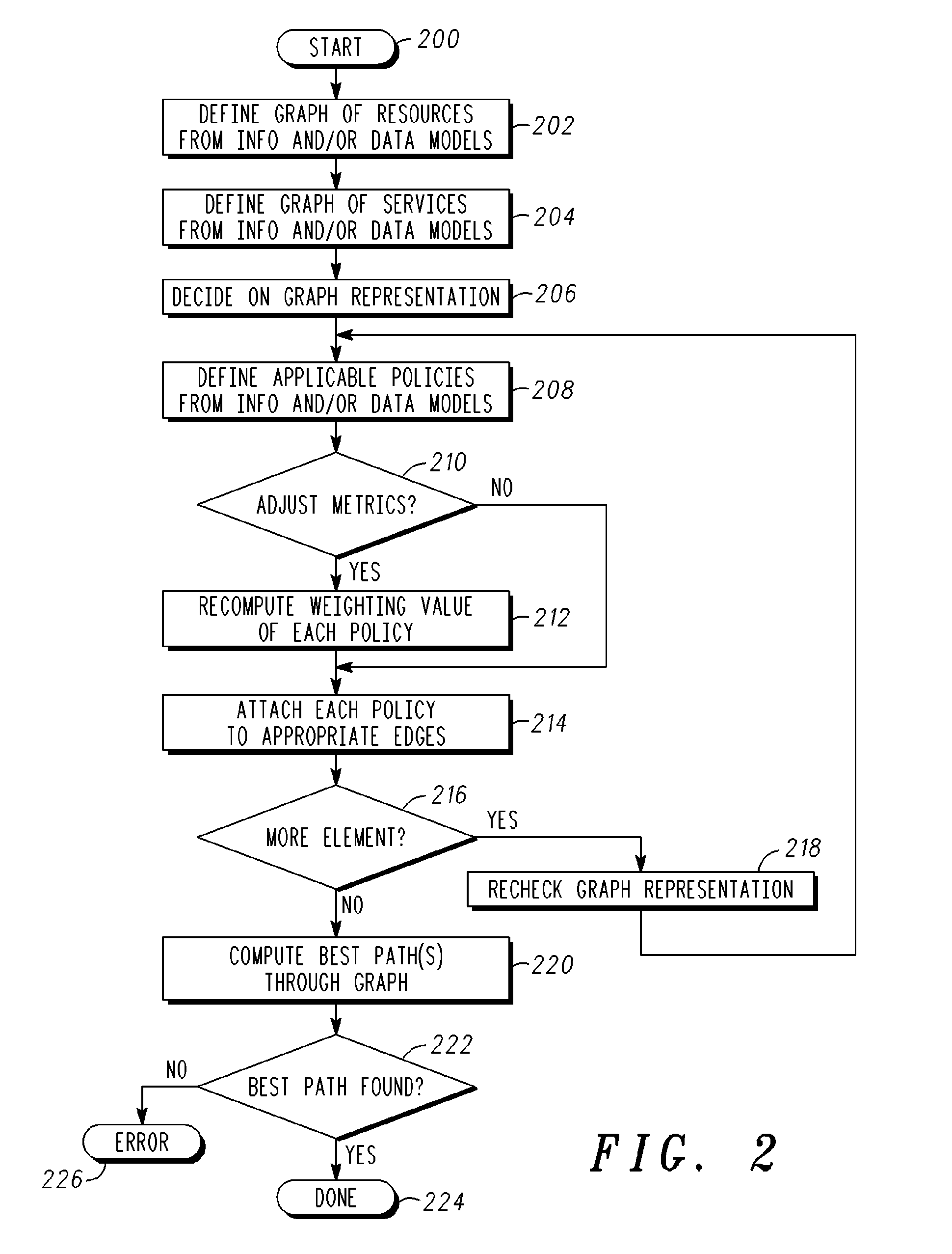
The patent describes a method and system for managing changes in a managed entity's state. The method involves creating a graph representation of each state change, with each state change represented as a separate node in the graph. The method also involves applying policies to each edge, which connects two nodes in the graph, to determine the cost of each edge. The method can also compare the cost of multiple paths and select the path with the lowest cost. Additionally, the method can utilize a policy to determine the permissibility of a state change. The system includes a graph representation of the managed entity's state changes and policies for managing the changes. The technical effects of the patent include improved management of state changes and better connectivity and communication between nodes in a graph.

Problems solved by technology

While orchestrating the behavior of a system can be guided by policies, changing business needs and environmental conditions change the policies used and their order of application in unforeseen ways.
However, static conditions lead to at least four important limitations in the art.
They are:1. inability to reorder policies to take into account changing business needs or environmental conditions (e.g., if a reconfiguration requires 3 separate steps that involve 3 different state changes, three different policies may be needed and the policies might need to be reordered to suit current business needs and / or environmental conditions);2. inability to adjust the applicability of a given policy (without changing its structure or content) to account for its varying relevance (e.g., as a function of changing context or business rules);3. inability to choose the best set of policies, among a set of applicable policies, that must be applied in a particular order, to move the system (or a component) to a new desired state; and4. inability to accommodate changing contexts.

Method used


Image

  • Graph-theoretic technique of analyzing and optimizing policy deployment
  • Graph-theoretic technique of analyzing and optimizing policy deployment
  • Graph-theoretic technique of analyzing and optimizing policy deployment

Examples


Embodiment Construction

[0028]As required, detailed embodiments of the present invention are disclosed herein; however, it is to be understood that the disclosed embodiments are merely exemplary of the invention, which can be embodied in various forms. Therefore, specific structural and functional details disclosed herein are not to be interpreted as limiting, but merely as a basis for the claims and as a representative basis for teaching one skilled in the art to variously employ the present invention in virtually any appropriately detailed structure. Further, the terms and phrases used herein are not intended to be limiting; but rather, to provide an understandable description of the invention.

[0029]The terms “a” or “an”, as used herein, are defined as one or more than one. The term “plurality”, as used herein, is defined as two or more than two. The term “another”, as used herein, is defined as at least a second or more. The terms “including” and / or “having”, as used herein, are defined as comprising (i...


PUM


Abstract

A method and a device for managing state changes (Init, Run, Suspend, Resume, End) of a managed entity (302) includes a memory (906) and a processor (904) adapted to represent each state change of a managed entity (302) as a separate node (1-5) in a graph (300), represent a state transition as an edge (Eij) connecting a first node with a first state value to a second node with a second state value, and determine a cost (C) of each edge (Eij) that is part of a set of edges (E) that form at least two paths connecting the first node and the second by applying at least one policy (P) to each edge (Eij), the first and second nodes representing an initial and a final state change of the managed entity (302).

Description

FIELD OF THE INVENTION[0001]This invention relates in general to policy management, and more particularly to structuring and reordering policies to adapt to changing business needs and environmental conditions using graph-theoretic techniques.BACKGROUND OF THE INVENTION[0002]Large systems can have a large number of policies that can interact in many different ways. While orchestrating the behavior of a system can be guided by policies, changing business needs and environmental conditions change the policies used and their order of application in unforeseen ways.[0003]There are currently no preferred ways of analyzing sets of policies to determine: if the order of application of policies is correct (let alone best); if the states visited by the set of policies are allowed (let alone optimal); what are the dependencies between each of the policies (including pre- and post-conditions and invariants); how the set of policies should change when business goals change; and how the set of p...

Claims


Application Information

Patent Timeline
Patent Type & Authority Applications(United States)
IPC IPC(8): G05B17/00
CPCG06Q10/04
Inventor STRASSNER, JOHN C.RAYMER, DAVID L.
Owner MOTOROLA INC
Learn More