HVAC Zone Controller

a controller and hvac technology, applied in the direction of electric controllers, static/dynamic balance measurement, instruments, etc., can solve the problems of ineffective or economic use of energy used to heat or cool these unoccupied rooms, the single thermostat location may not accurately represent the heating or cooling needs of the structure, and the heating and cooling load of individual areas of the structure may not be satisfied

Active Publication Date: 2008-07-03
ADEMCO INC
View PDF42 Cites 149 Cited by
  • Summary
  • Abstract
  • Description
  • Claims
  • Application Information

AI Technical Summary

Problems solved by technology

However, a single thermostat location may not accurately represent the heating or cooling needs throughout the structure.
As a consequence, the heating and cooling loads of individual areas of the structure may not be satisfied and the temperature of these areas will tend to deviate from the desired temperature.
Energy that is used to heat or cool these unoccupied rooms is not used effectively or economically.
However, a system that has only a single thermostat is generally unable to accurately control different locations in the building at different temperatures.
Although it is possible that each of these thermostats could control a separate fluid temperature modifying device such as a separate furnace or air conditioner for each zone, such an approach is generally neither efficient nor economical.
While this control may be as simple as turning on the heating or cooling device and opening the damper or valve for a particular zone any time the thermostat from that zone calls for space conditioning, often times more complex control strategies are desired.
Even relatively simple zone control schemes require substantial electronic circuitry to implement.
Where more complex control strategies are used, even greater amounts of electronic circuitry are required.

Method used


Image

  • HVAC Zone Controller
  • HVAC Zone Controller
  • HVAC Zone Controller

Examples


Embodiment Construction

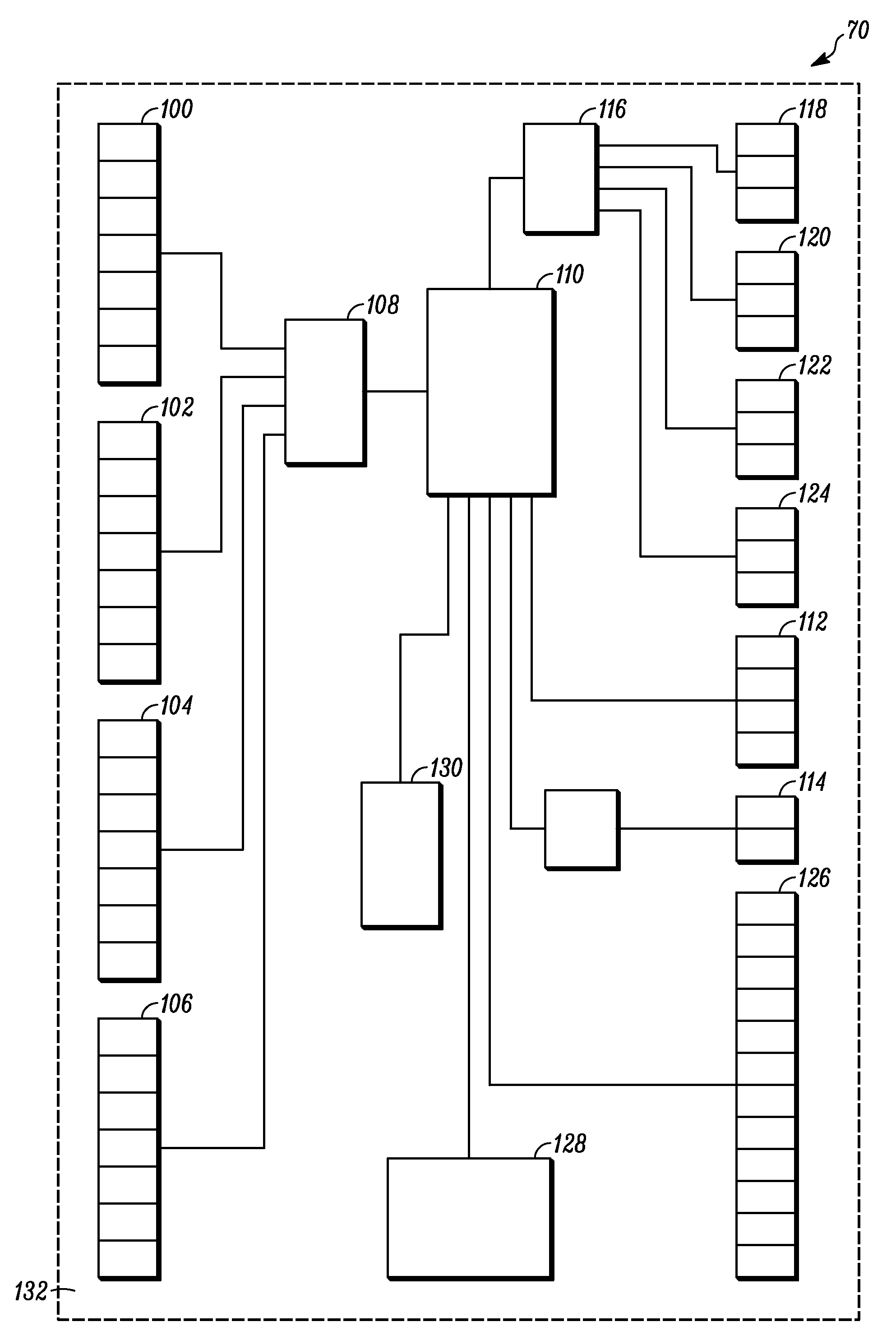
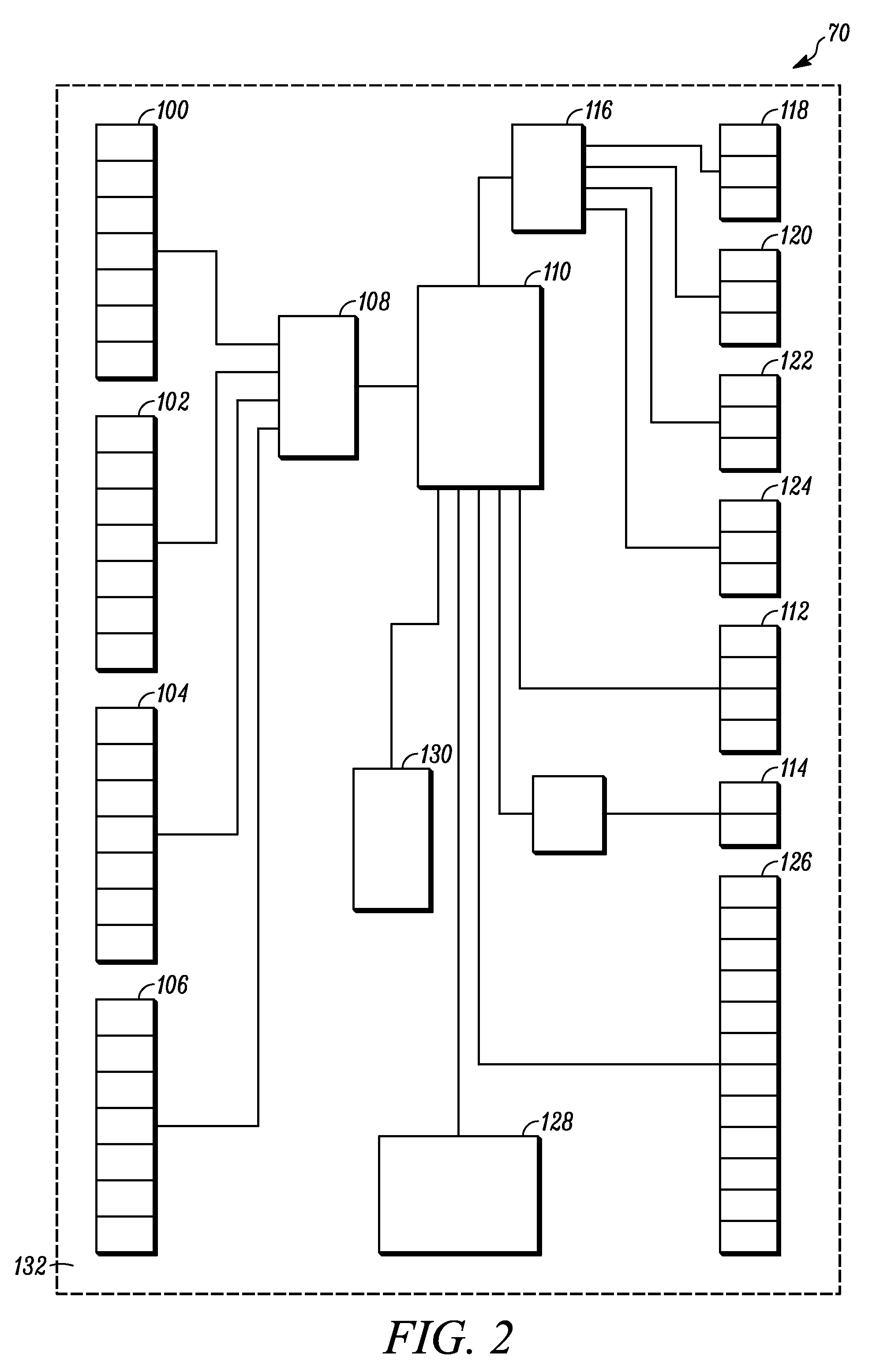
[0021]A zone controller must ultimately be installed in a building and operated in order to be useful. However, despite the fact that many installers have training in the installation of HVAC components, the task of installing a zone controller can be difficult. This difficulty is related in part to the complexity of the zone controller itself. Because the configuration of the HVAC equipment can vary considerably from one building to the next, zone controllers are often provided with the capability to adapt to a wide variety of equipment configurations. However, this adaptability often requires that the installer make a number of selections or adjustments to the zone controller itself. The need for adaptability also often increases the complexity of the controller and the number of electronic components that are part of the zone controller. The end result is that the zone controller may have a large number of electronic components, some of which the installer is required to manipula...


PUM


Abstract

A zone controller having an electronic board with a plurality of electronic components attached thereto. The electronic components are constructed and arranged to receive a plurality of signals from a plurality of thermostats and to transmit a plurality of signals to a plurality of air control devices for controlling airflow in ducts. The electronic components include a first grouping of electronic components that are not accessed to perform either installation or operation functions, a second grouping of electronic components that are accessed to perform installation functions, and a third grouping of electronic components that are only accessed to perform operation functions. A first cover is provided that covers and prevents access to the first grouping of electronic components. A second cover is provided that selectively covers and prevents access to the second grouping of electrical components but not the third grouping of electrical components.

Description

FIELD OF THE INVENTION [0001]The invention relates to heating, ventilation, and air conditioning (HVAC) equipment, and more particularly, to zone controllers for HVAC systems.BACKGROUND OF THE INVENTION [0002]Many buildings, particularly relatively small buildings such as single-family houses, have a single HVAC unit that is controlled by a single thermostat. The HVAC unit typically comprises some type of fluid temperature modifying device, such as a furnace for heating air, a boiler for heating a liquid or steam, or an air conditioner having an evaporating coil for cooling air. If the fluid is air, it is typically ducted to various locations within the building, or if it is liquid or steam, it is typically piped to heat exchangers at various locations in the building. The thermostat in this type of space conditioning system is typically positioned at a location where the heating and cooling loads are representative of the entire structure. For example, the thermostat may be install...

Claims


Application Information

Patent Timeline
Patent Type & Authority Applications(United States)
IPC IPC(8): G05B13/00
CPCF24F13/20F24F11/0012F24F11/30F24F2110/10F24F11/52F24F11/76F24F11/88F24F11/46F24F11/63
Inventor TAKACH, EUGENE J.SCHWENDINGER, PAUL G.MULHOUSE, DAVID P.TRIFILIO, CHRISTIAN RICHARDCARREON, RONALDO FERNANDEZCLEMENTS, DANIEL VINCENT
Owner ADEMCO INC
Why Eureka
Try Eureka