Suture anchor and inserter arrangement

a technology of anchoring and inserting, which is applied in the field of suture anchoring and inserting arrangement, can solve the problems of of providing conventional rigid eyelets which are formed, and the anchor body as discussed above is difficult, if not impossibl

Inactive Publication Date: 2008-07-10
STRYKER CORP
View PDF72 Cites 79 Cited by
  • Summary
  • Abstract
  • Description
  • Claims
  • Application Information

AI Technical Summary

Problems solved by technology

Providing conventional rigid eyelets which are formed integrally with the anchor body as discussed above is difficult if not impossible on such a small scale.

Method used


Image

  • Suture anchor and inserter arrangement
  • Suture anchor and inserter arrangement
  • Suture anchor and inserter arrangement

Examples


Embodiment Construction

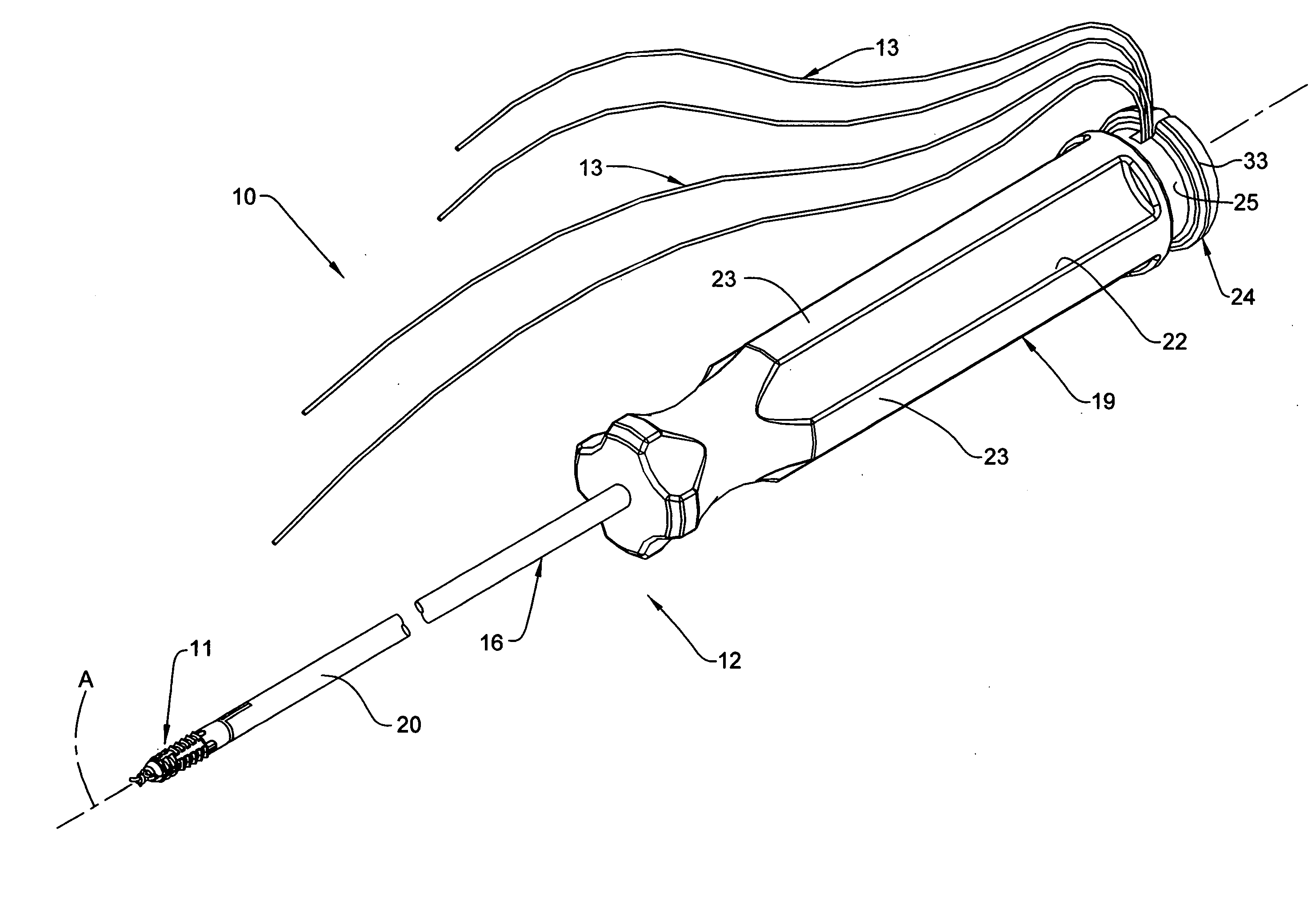
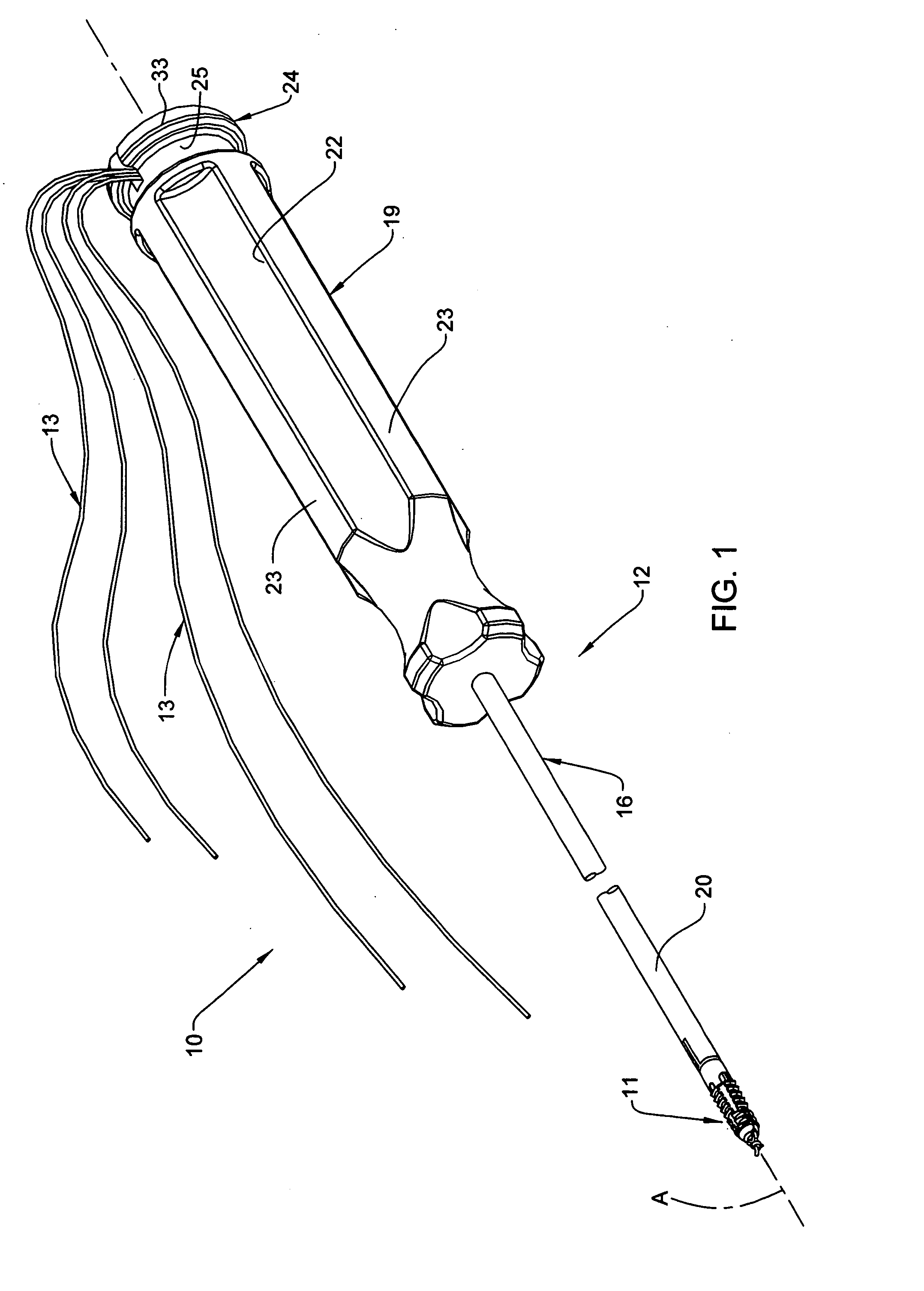
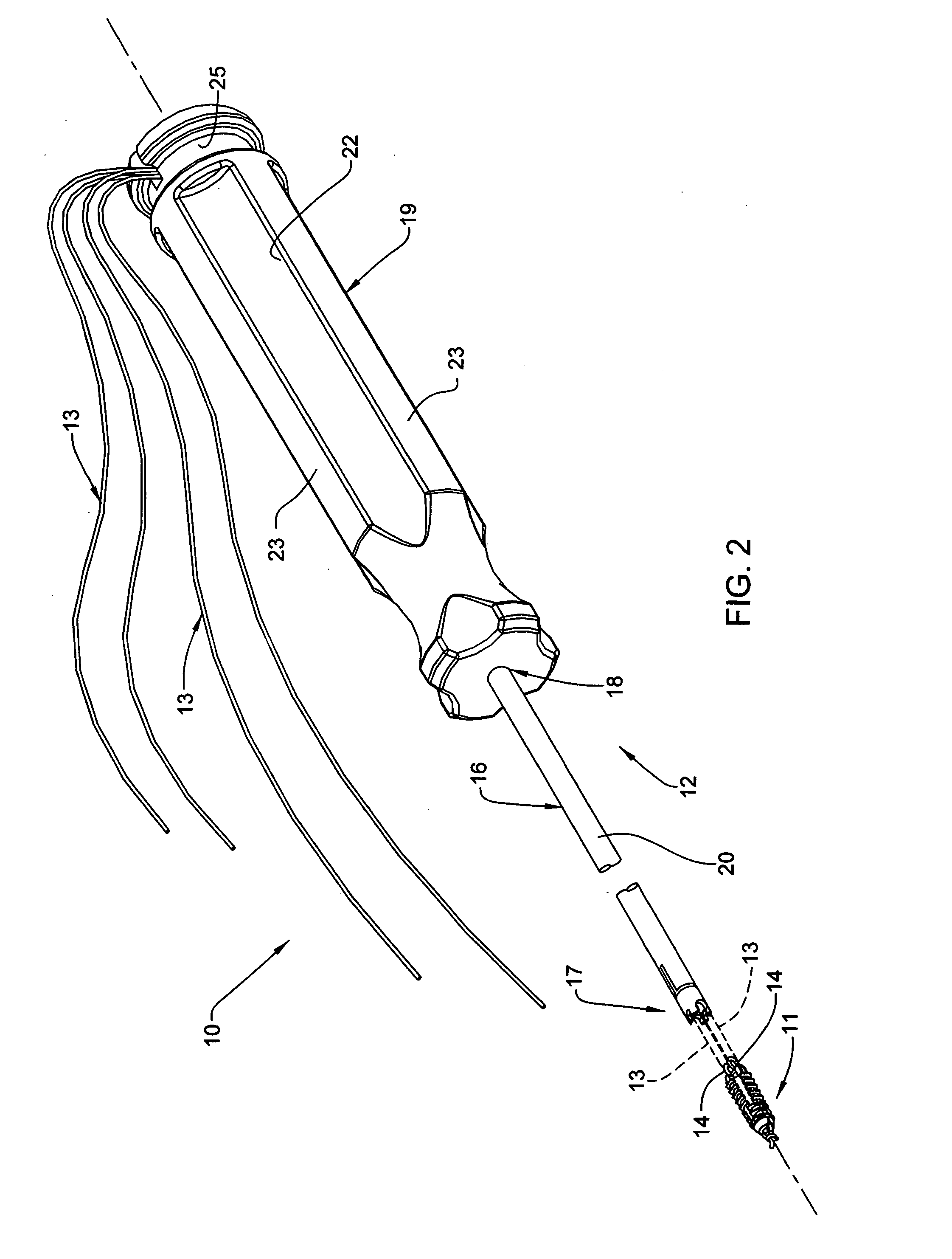
[0029]Referring to FIGS. 1 and 2, a suture anchor and inserter arrangement 10 is illustrated which is generally elongated in shape and defines a central longitudinal axis “A”. The arrangement 10 generally includes a suture anchor 11 initially supported on an inserter device 12. Working sutures 13 extend through the inserter device 12 and cooperate with eyelets 14 defined at the proximal end of the suture anchor 11.

[0030]The inserter device 12 is defined by an elongate and rigid inserter shaft 16 having a distal end 17 which engages the suture anchor 11, and a proximal end 18 fixed to a handle 19. Inserter shaft 16 includes a tubular sidewall 20 which defines a bore 21 extending throughout the longitudinal length of shaft 16 (FIG. 6). Handle 19 has an outer surface defining therein a series of axially or longitudinally extending recesses or depressions 22, wherein each circumferentially adjacent pair of recesses 22 are separated by a longitudinally extending projection 23. The altern...


PUM


Abstract

A suture anchor and inserter arrangement, including a suture anchor configured for implanting in hard tissue, such as bone, and an inserter device for installing the anchor in hard tissue. The suture anchor includes at least one eyelet formed from suture material at a proximal end thereof, which eyelet cooperates with a working suture associated with the inserter device. The working suture is engaged with the eyelet of the implanted anchor, and can be utilized to anchor soft tissue to hard tissue.

Description

FIELD OF THE INVENTION[0001]This invention relates to a suture anchor and inserter arrangement for use in fixing surgical suture to bone.BACKGROUND OF THE INVENTION[0002]During some injuries, soft tissue, such as tendons or ligaments, can tear away from hard tissue, such as bone. Accordingly, it becomes necessary to reattach the soft tissue to the bone in order to facilitate the healing process. Various types of devices are used to reattach tissue, such as screws, staples and suture anchors. The instant invention relates to this latter type of attachment device.[0003]Suture anchors may be inserted into a preformed hole made in the hard tissue, while other anchors are self-tapping. The anchors typically include an eyelet through which lengths of repair suture or working suture are threaded, which working suture is inserted simultaneously with the anchor into the hard tissue. In this regard, an inserter device or driver may be utilized in conjunction with the anchor to install or driv...

Claims


Application Information

Patent Timeline
Patent Type & Authority Applications(United States)
IPC IPC(8): A61B17/04
CPCA61B17/0401A61B2017/0409A61B2017/0412A61B2017/0458A61B2017/0427A61B2017/0445A61B2017/0414
Inventor MOREAU, NATHAN RYANSINNOTT, MARGARET MARYMILLER, M. TODD
Owner STRYKER CORP
Why Eureka
Try Eureka