Knee Pad

a technology of knee pads and knee pads, which is applied in the field of knee pads, can solve the problems of not staying properly aligned, uncomfortable for the wearer, and defeating the purpose of the device, and achieve the effect of better conformation

Active Publication Date: 2008-07-17
RICHARDS LEE E
View PDF22 Cites 18 Cited by
  • Summary
  • Abstract
  • Description
  • Claims
  • Application Information

AI Technical Summary

Benefits of technology

[0007]The invention is a knee pad to be used in conjunction with a knee-pad support frame. The knee pad has strap ears that are curved to better conform to the user's leg, when the

Problems solved by technology

One of the problems of conventional knee pad devices is that they do not stay properly align

Method used


Image

  • Knee Pad
  • Knee Pad
  • Knee Pad

Examples


Embodiment Construction

[0012]The present invention will now be described more fully in detail with reference to the accompanying drawings, in which the preferred embodiments of the invention are shown. This invention should not, however, be construed as limited to the embodiments set forth herein; rather, they are provided so that this disclosure will be complete and will fully convey the scope of the invention to those skilled in the art.

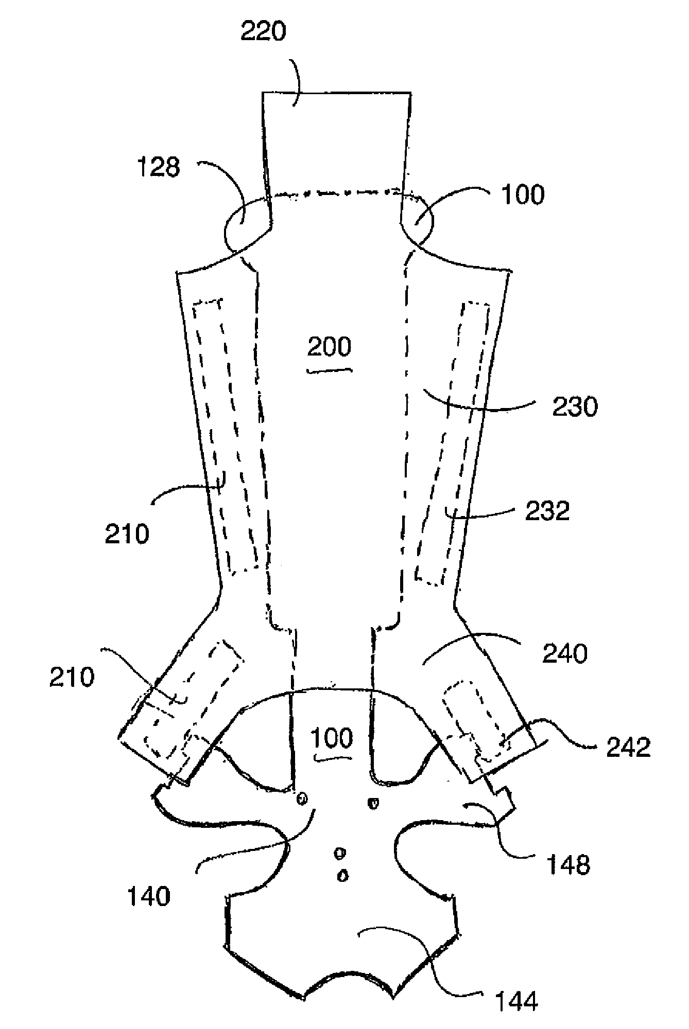
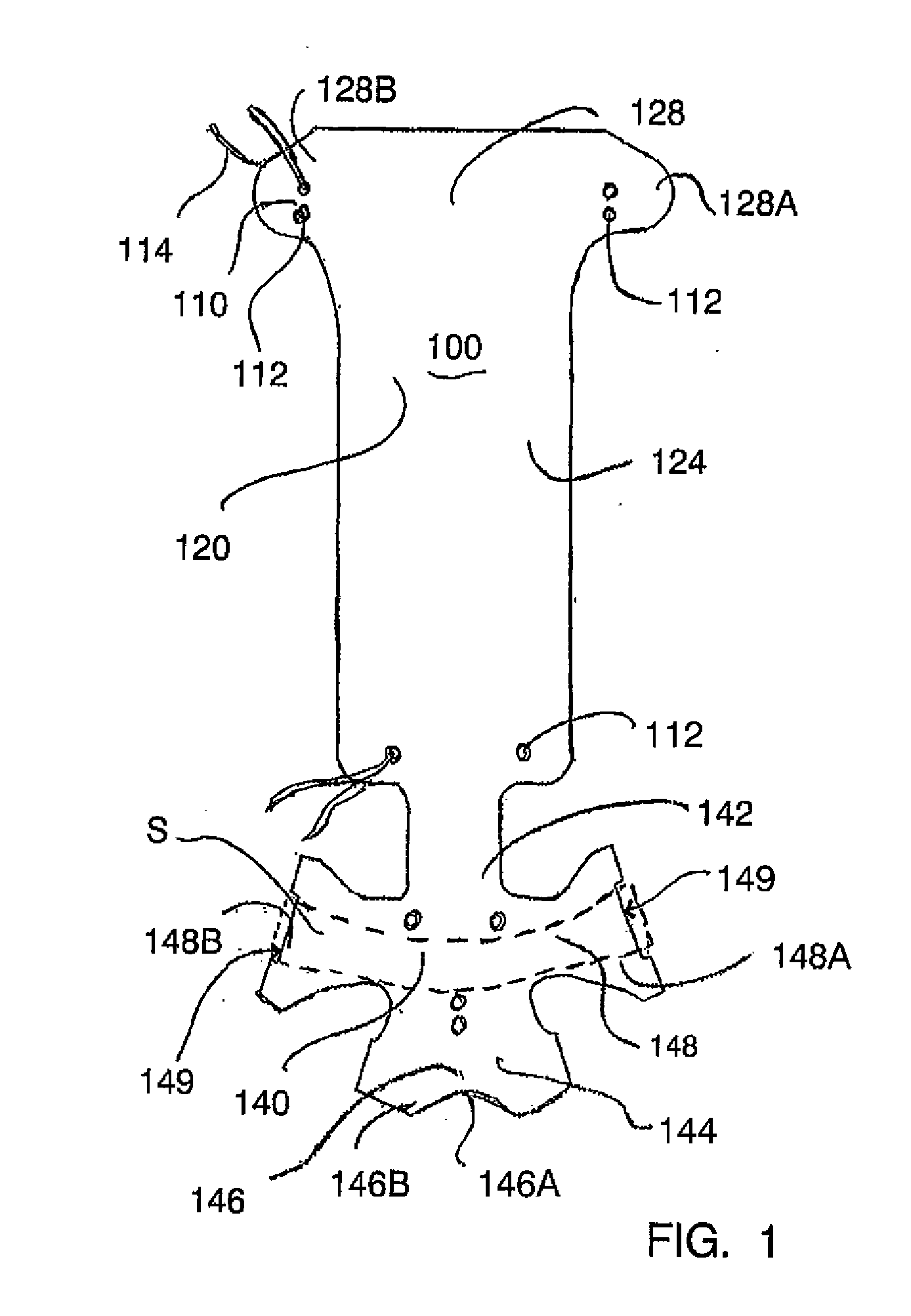
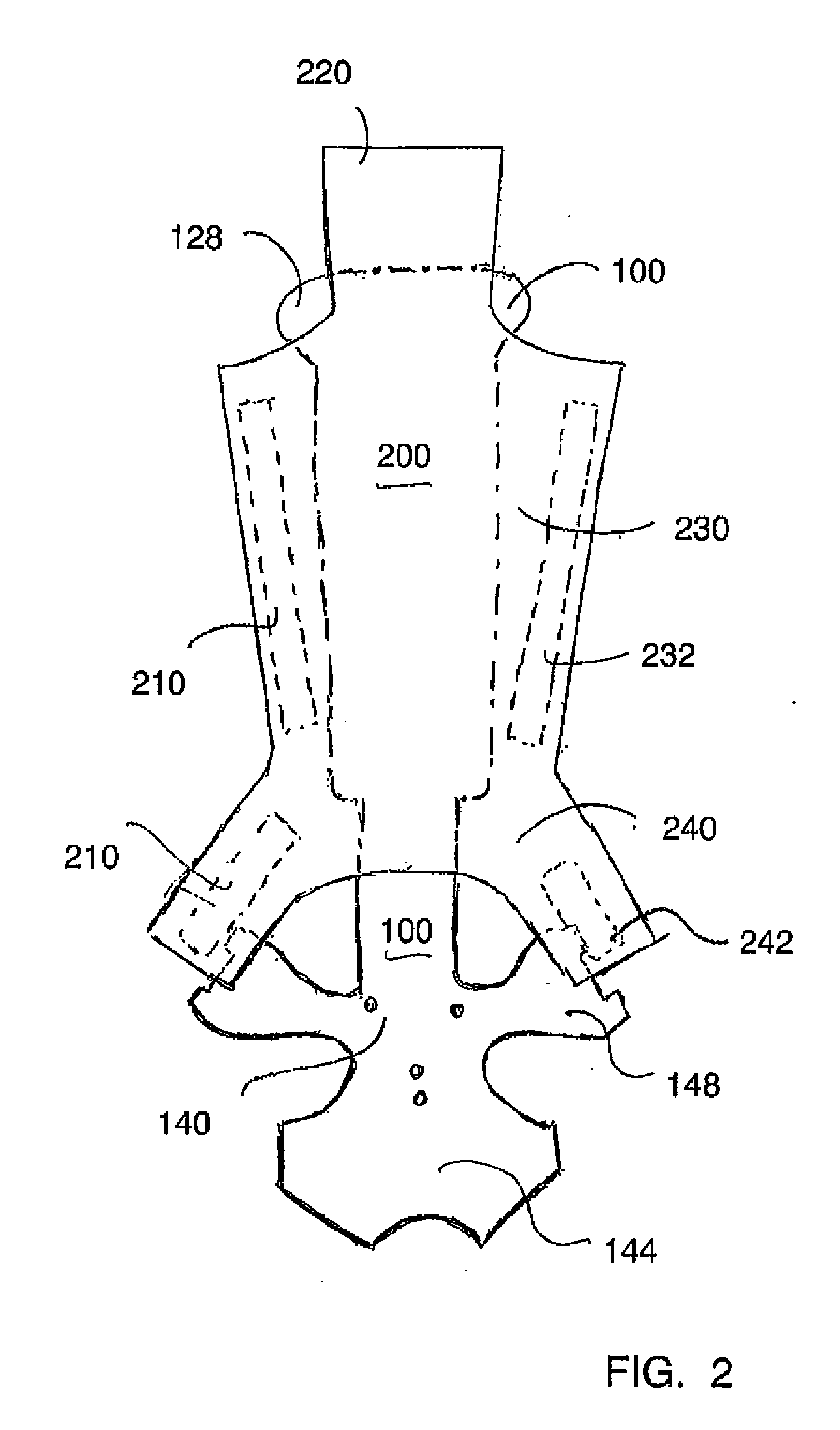
[0013]FIG. 1 illustrates a knee pad 100 according to the invention. The knee pad 100 is used in conjunction with a known support frame, such as the support frame described in U.S. Pat. No. 4,876,745. The support frame on which the knee pad 100 according to the invention is installed is very similar to the support frame shown in the U.S. patent just cited, but has a truncated fork section. In other words, the prongs shown as “19” in the older frame have been shortened, so that the truncated fork section straddles the top of the user's boot, but prongs do not extend very f...


PUM


Abstract

A knee pad with a support frame, a pad, and a boot. The pad is assembled on the support frame to provide a cushioning surface between the support frame and the wearer's leg. The pad has ears in the knee section and in the ankle section, which serve to maintain the support frame and pad in proper alignment on the leg. The boot provides a non-slip, non-marring surface against the floor, when the wearer is working in a kneeling position. A moisture-absorbent liner, which is easily removed for cleaning or replaceable, may also be fitted on top of the pad, to provide an absorbent layer between the pad and the wearer's leg.

Description

BACKGROUND INFORMATION[0001]1. Field of the Invention[0002]The invention relates to the field of knee pads. More particularly, the invention relates to knee pads mounted on a support frame that is strapped to the leg of a user.[0003]2. Description of the Prior Art[0004]Many types of installation and construction work require that a person spend an extended period of time in a kneeling position. For example, people who install carpeting or flooring typically work in a kneeling position on a hard surface. Knee pads are generally worn for such tasks, to protect the knees. Knee pad devices are known, that include a support frame and a pad and that protect not only the knee, but also the shin and ankle portions of the leg. U.S. Pat. Nos. 4,772,071 and 4,876,745 disclose such knee pad devices. These patents were issued to the inventor of the present application and their disclosures are incorporated herein by reference in their entirety.[0005]One of the problems of conventional knee pad d...

Claims


Application Information

Patent Timeline
IPC IPC(8): A41D13/06
CPCA41D13/065
Inventor RICHARDS, LEE E.
Owner RICHARDS LEE E
Why Eureka
Try Eureka