

Filler Neck Closure
a neck closure and seal technology, applied in the direction of caps, sealing, liquid handling, etc., can solve the problems of increasing the required force to overcome the friction between the contacting surfaces, and the connection suffers, so as to reduce the risk of the seal sticking to the seal seat and significantly reduce the force required to remove the closure
- Summary
- Abstract
- Description
- Claims
- Application Information
AI Technical Summary
Benefits of technology
Problems solved by technology
Method used
Image

Examples
Embodiment Construction
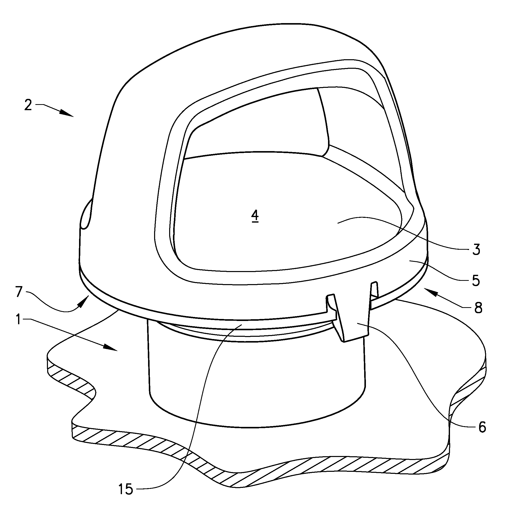
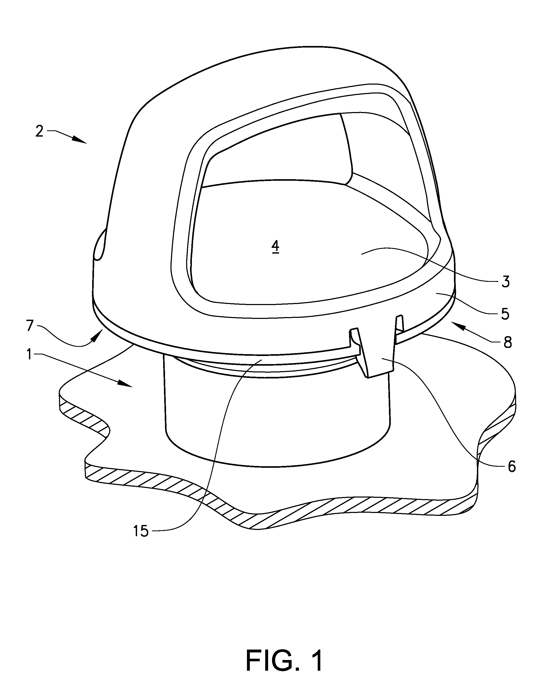
[0024]FIG. 1 shows a filler neck 1 with a closure 2 according to a first embodiment of the invention. According to this embodiment, the closure is an oil filler cap 2 engageable with an oil filler neck 1 on an internal combustion engine. The oil filler cap 2 has a cup-shaped body having a top 3 with an upper surface 4 facing the user and a peripheral wall 5. The peripheral wall 5 is provided with releasable fastening elements in the shape of resilient tongues 6, 7, 8 arranged for interaction with the filler neck 1. The embodiment shows an oil filler cap 2 held in place by three resilient tongues 6, 7, 8 (one shown). The resilient tongues 6, 7, 8 will be described in further detail in connection with FIGS. 3 and 4. Peripheral wall 5 shown in this example is cylindrical and substantially concentrically mounted onto filler neck 1. In this example, three resilient tongues 6, 7, 8 are integrated in and extend axially from the peripheral wall 5.
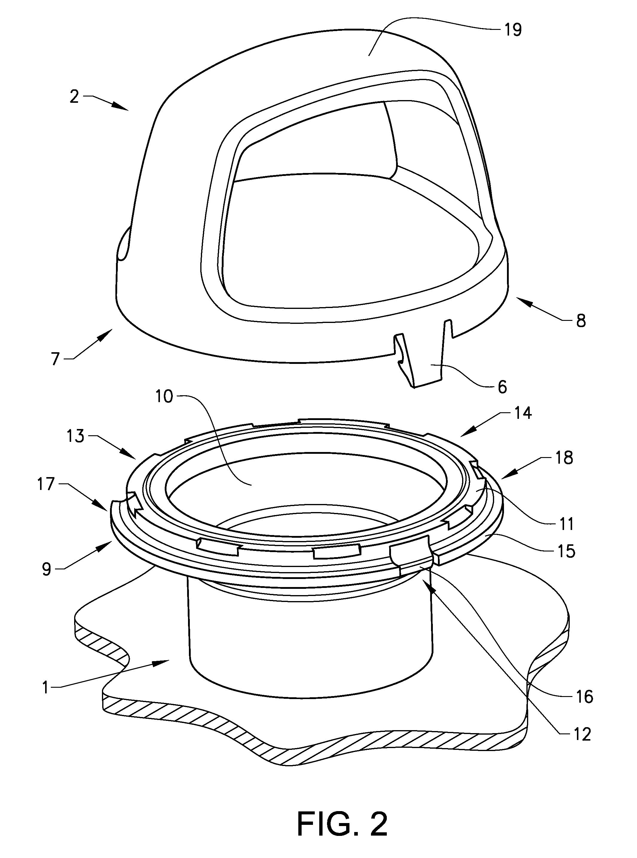
[0025]FIG. 2 shows the filler neck 1 of FIG....
PUM
 Abstract
Description
Claims
Application Information