Needle hub assembly

Inactive Publication Date: 2008-07-17
KNUTSON ERIC J
View PDF37 Cites 24 Cited by
  • Summary
  • Abstract
  • Description
  • Claims
  • Application Information

AI Technical Summary

Benefits of technology

[0019](d) The deflector does not add substantially to the cost of a needle-hub assembly
[0020]Further objects and advantages are to provide a needle hub assembly that does not alter user technique, and does not distract the user, in order to prevent needle breakage.
[0021]Still further objects and advantages will become apparent from a consideration of the ensuing description and drawings.
[0022]In the drawings, closely related figures have the same number, but different alphabetic suffixes.
[0023]FIG. 1 is a cross-section

Problems solved by technology

Needle breakage remains a problem in healthcare and veterinary care.
Although greatly reduced by the advent of disposable needles, needle breakages still occur, and generally result in a minor surgical procedure being required to extricate the needle fragment.
Needles tend to break near the hub.
Most often, they break because the needle is bent during use, both intentionally and unintentionally.
The problem with broken needles occurs when the needle is inserted fully and the hub is pushing against the tissues.
Non-surgical attempts to retrieve the fragment generally result in pushing it deeper into the tissues .
In humans, broken needle incidents tend to result in litigation.
In animals, anesthesia and surgery is costly, or worse, sometimes the broken needles are simply left in the animal, which causes a detection problem for the meat indus

Method used


Image

  • Needle hub assembly
  • Needle hub assembly
  • Needle hub assembly

Examples


Example

EXAMPLE 1

[0052]User selects a needle hub assembly having a flexible deflector 10 which is connected directly to hub 14, as shown in FIGS. 1, 2, and 3. User refers to indicator 18 to identify the angle of the needle bevel, and decides the angulation of the needle bend. User applies lateral pressure against needle 12, and flexible deflector 10 flexes to permit needle 12 to bend proximal to hub 14.

[0053]User forcefully inserts the full distal portion of needle 12 into the tissues until stop 16 portion of deflector 10 pushes against the tissues, thereby displacing the tissues away from the advancing hub 14 until the insertion of needle 12 is halted. Deflector 10 protrudes from the tissues, and the proximal portion of needle 12 and hub 14 are held away from the insertion point of the distal portion of needle 12 into the tissues.

[0054]By chance, needle 12 separates adjacent to hub 14 at the location of the bend. Deflector 10 remains connected to the portion of needle 12 that is distal fro...

Example

EXAMPLE 2

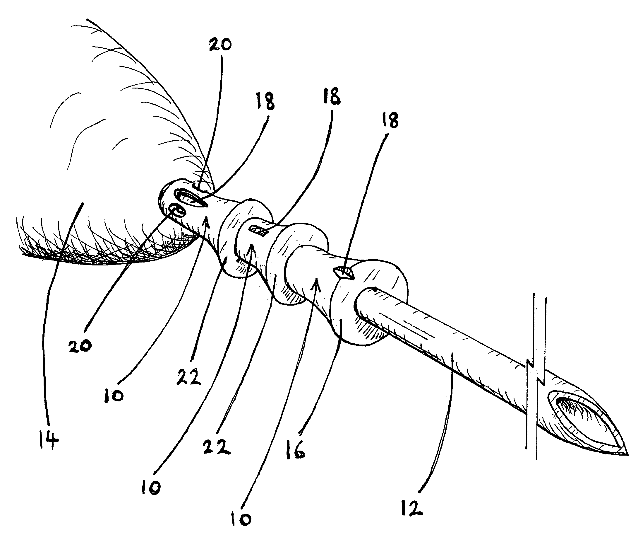
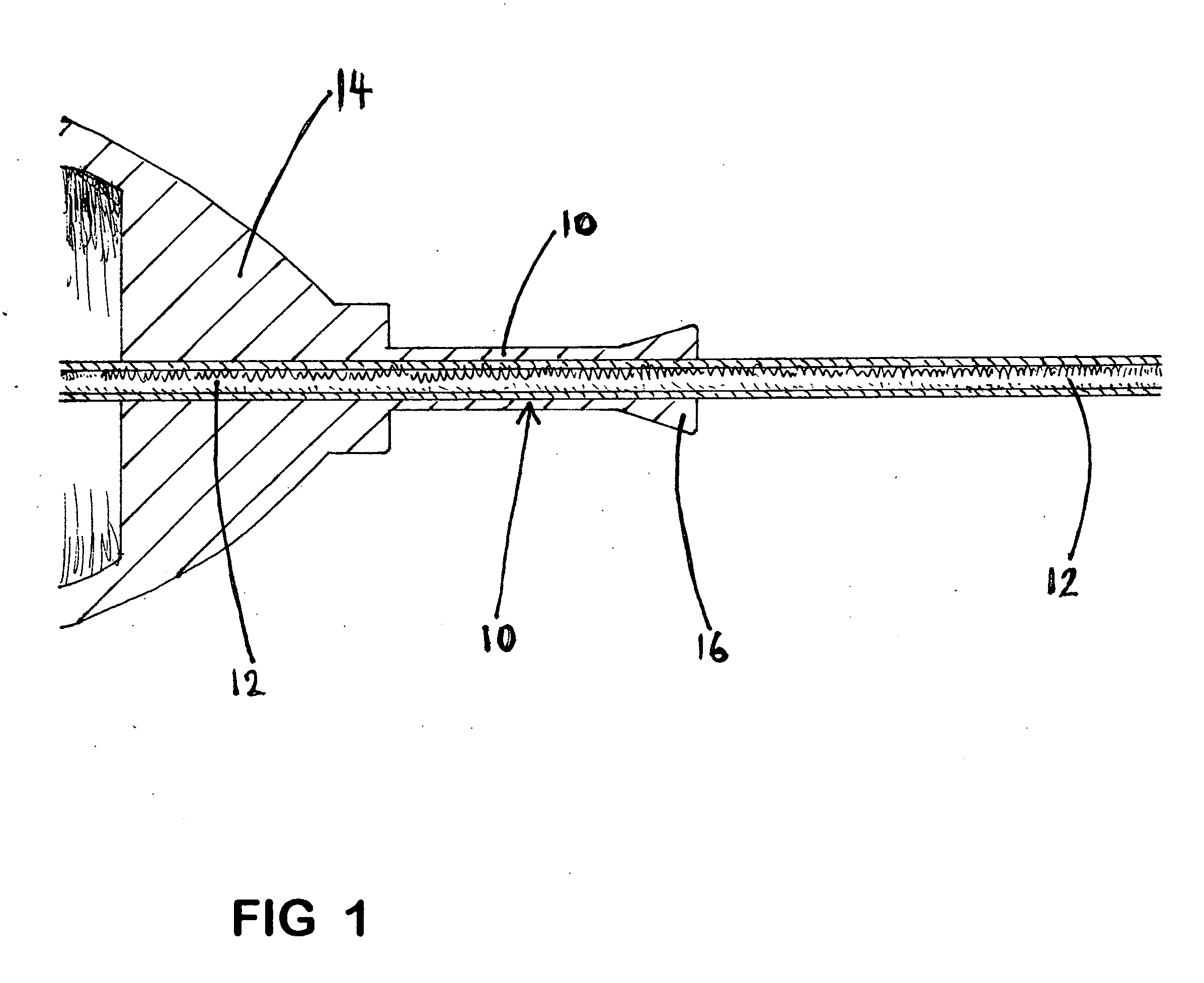
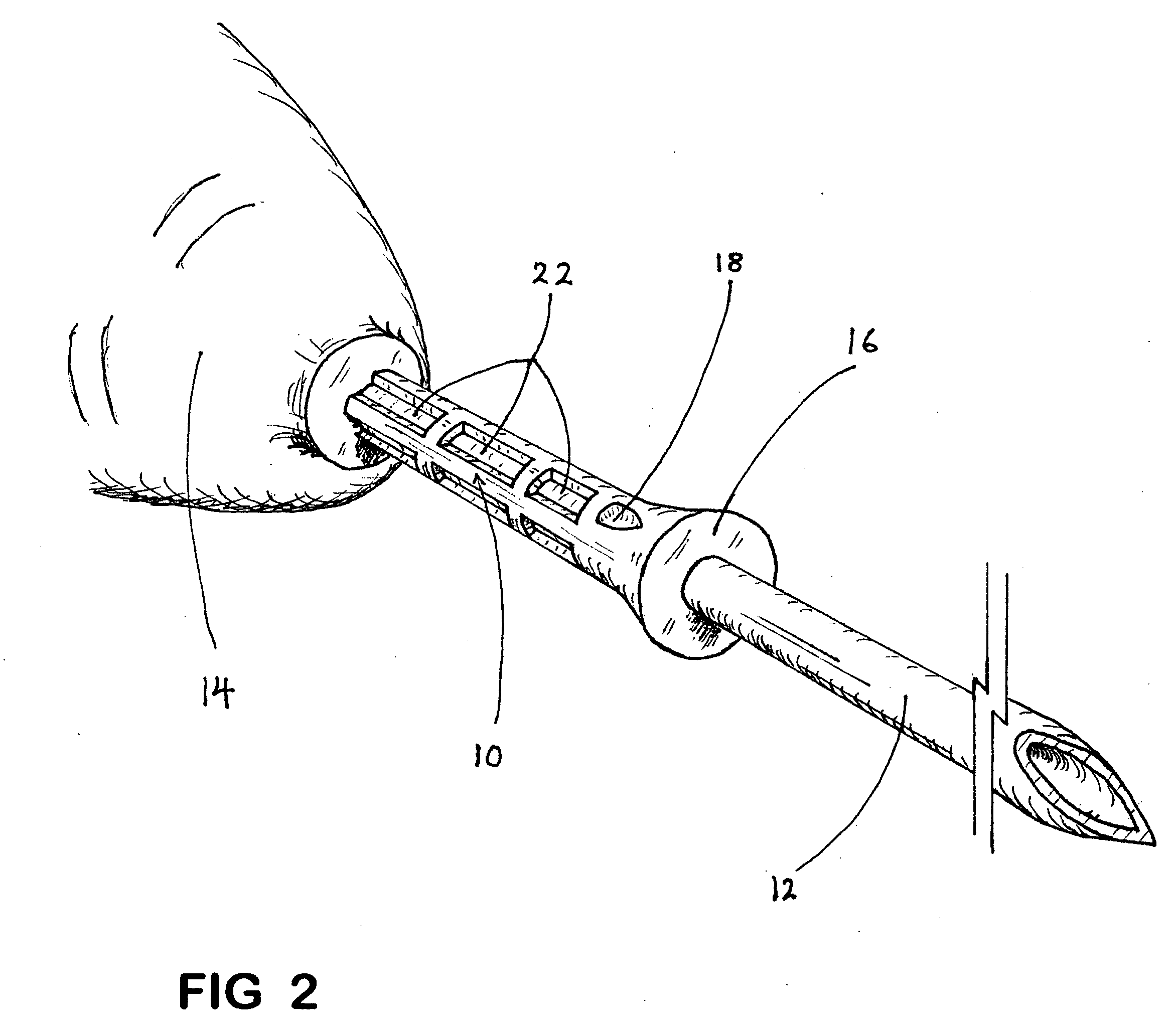
[0056]User selects a standard needle hub assembly having no deflector 10. User selects a separate sleeve-shaped deflector 10 having a central lumen for receiving a needle. User inserts needle 12 into the lumen of deflector 10, and slides deflector 10 along needle 12 until it is in close proximity to hub 14, as shown in FIG. 4A. Deflector 10 is then connected to needle 12 by friction, but deflector 10 is not connected to hub 14. User applies lateral pressure against needle 12, and deflector 10 permits needle 12 to bend proximal to hub 14.

[0057]User forcefully inserts the full distal portion of needle 12 into the tissues until stop 16 portion of deflector 10 pushes against the tissues, thereby displacing the tissues away from the advancing hub 14 until the insertion of needle 12 is halted. Deflector 10 protrudes from the tissues, and the proximal portion of needle 12 and hub 14 are held away from the insertion point of the distal portion of needle 12 into the tissues.

[0058]By...

Example

EXAMPLE 3

[0060]User connects a needle hub assembly having a deflector 10 which is not connected to hub 14, as shown in FIGS. 4B and 4C. User applies lateral pressure against needle 12, and deflector 10 permits needle 12 to bend proximal to hub 14.

[0061]User forcefully inserts the full distal portion of needle 12 into the tissues until deflector 10 pushes against the tissues, thereby displacing the tissues away from the advancing hub 14 until the insertion of needle 12 is halted. Deflector 10 protrudes from the tissues, and the proximal portion of needle 12 and hub 14 are held away from the insertion point of the distal portion of needle 12 into the tissues.

[0062]By chance, needle 12 separates from hub 14 proximally to hub 14. Deflector 10 remains connected to needle 12 distal from the point of separation.

[0063]When user withdraws hub 14 away from the tissues, hub 14 separates from deflector 10 and broken needle 12, but deflector 10 remains connected to needle 12. As the pressure exe...


PUM


Abstract

A needle-hub assembly, the improvement comprising a small tissue deflector connected to the needle, wherein the deflector deflects tissues away from the hub to prevent needle penetration to the hub, but permits the needle to bend adjacent to the hub, thereby enhancing the retrievability of the needle from the tissues if the needle were to separate.

Description

BACKGROUND[0001]1. Field of Invention[0002]This invention relates to healthcare and veterinary care, specifically to needles.[0003]2. Description of Prior Art[0004]Needle breakage remains a problem in healthcare and veterinary care. Although greatly reduced by the advent of disposable needles, needle breakages still occur, and generally result in a minor surgical procedure being required to extricate the needle fragment.[0005]Needles tend to break near the hub. Most often, they break because the needle is bent during use, both intentionally and unintentionally. The problem with broken needles occurs when the needle is inserted fully and the hub is pushing against the tissues. When a fully inserted needle breaks off, the tissues tend to close over the insertion point hole as the hub is withdrawn, thereby covering the needle fragment. Non-surgical attempts to retrieve the fragment generally result in pushing it deeper into the tissues .[0006]To accomplish surgical recovery of the need...

Claims


Application Information

Patent Timeline
IPC IPC(8): A61M5/00
CPCA61M5/329
Inventor KNUTSON, ERIC J.
Owner KNUTSON ERIC J
Why Eureka
Try Eureka