Aircraft refuelling system

Inactive Publication Date: 2008-07-24
AIRBUS OPERATIONS LTD
View PDF18 Cites 21 Cited by
  • Summary
  • Abstract
  • Description
  • Claims
  • Application Information

AI Technical Summary

Benefits of technology

[0008]The present invention seeks to provide an aircraft refuelling system that allows the refuelling rate to be increased while not prejudicing the safety of the fuel tank i

Problems solved by technology

If an overflow occurs and fuel is forced through the vent system the pressure increase is higher due to the increased drag of fuel through the vent system.
This increase in strength leads to

Method used


Image

  • Aircraft refuelling system
  • Aircraft refuelling system
  • Aircraft refuelling system

Examples


Embodiment Construction

[0043]The embodiment of the invention provides an improved aircraft refuelling system to allow faster refuelling times.

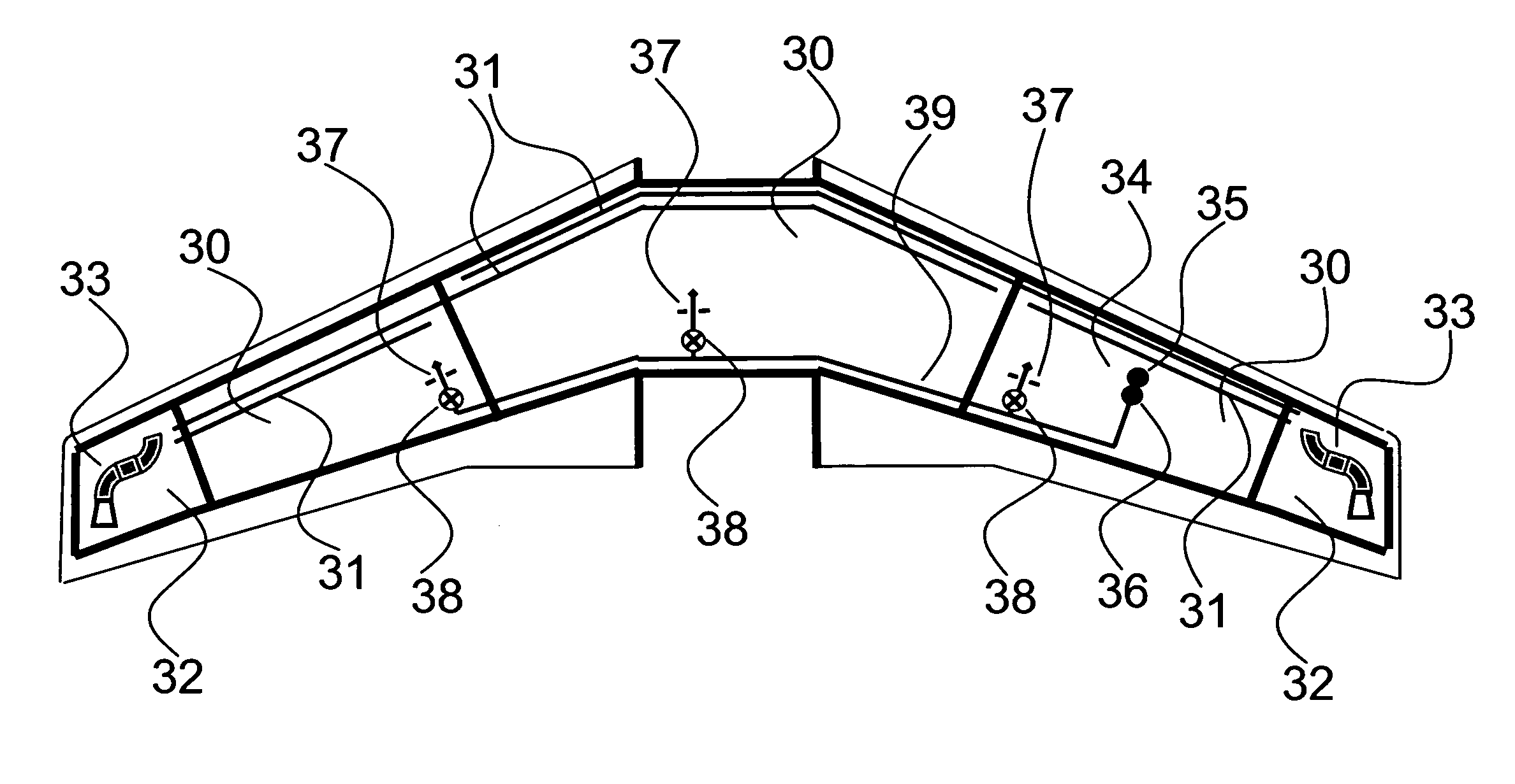
[0044]FIG. 3 is a schematic diagram of an aircraft refuelling system according to an embodiment of the present invention. The aircraft has fuel tanks 30 located in the fuselage and wings, which tanks are connected to vent pipework 31 to allow air (or inert gas) to flow out of the tanks 30. In the case of fuel overflow, fuel may be caused to flow through the vent pipework 31 as it is forced out of the fuel tanks 30. Two vent pipes are provided for the centre tank, each having an inlet at one side of the centre tank and an outlet to the vent tank located on the opposite side of the aircraft to the inlet. The vent pipework 31 is open to vent tanks 32 such that fuel passing through the vent pipework during an overflow is caught by the vent tanks 32. The pipework also vents to the exterior of the aircraft via flame arrestors 33 to allow air to escape from the fuel tanks ...


PUM


Abstract

An aircraft refuelling system of an aircraft is provided. The refuelling system comprises a refuelling connector (34) mounted as part of the aircraft and configured to detachably connect to the fuel outlet (2) of a fuel supply apparatus separate from the aircraft, and a fuel pressure regulator (36) having an inlet in communication with a fuel inlet (35) of the refuelling connector (34) and having an outlet in communication with refuelling pipework (39) of the aircraft. The fuel pressure regulator (36), regulates the pressure of fuel in the refuelling pipework (39) when fuel is being passed into the refuelling pipework (39) from the fuel inlet (35) of the refuelling connector. A fuel pressure regulator apparatus for mounting in an aircraft, comprising a connector forming a fuel inlet to the fuel pressure regulator apparatus, configured to detachably connect to the fuel outlet of a fuel supply system, a fuel outlet for connection to the refuelling pipework of an aircraft and a fuel pressure regulator for regulating the pressure of fuel passing through the fuel outlet is also provided.

Description

BACKGROUND OF THE INVENTION[0001]The present invention relates to refuelling / defuelling equipment on board an aircraft, particularly but not necessarily exclusively, an aircraft having onboard refuelling / defuelling equipment comprising internal fuel-flow restrictors.[0002]Aircraft are refuelled at airports between flights with the amount of fuel required to complete their next flight. In order to maximise the revenue generated by an aircraft it is desirable to maximise the flying time of the aircraft and minimise the time spent on the ground between flights. The time spent refuelling an aircraft is a significant contributor to the time required between flights and therefore it is desirable to minimise that refuelling time.[0003]Aircraft are refuelled using ground equipment such as that shown in FIG. 1. An aircraft's refuelling system is connected to a fuel hose 1 by a hose end coupling 2 and fuel is pumped from a fuel storage tank 3 by fuel pump 4 into the aircraft. Two stages of pr...

Claims


Application Information

Patent Timeline
IPC IPC(8): B64D37/14
CPCB64D37/16Y02T50/44B64D37/20Y02T50/40Y10T137/3421Y10T137/7793
Inventor CROWLEY, MICHAEL
Owner AIRBUS OPERATIONS LTD
Why Eureka
Try Eureka