QKD system with link redundancy

a technology of link redundancy and qkd, applied in the direction of digital transmission, secret communication, electrical equipment, etc., can solve the problem of expensive approach

Inactive Publication Date: 2008-07-24
MAGIQ TECH INC
View PDF2 Cites 63 Cited by
  • Summary
  • Abstract
  • Description
  • Claims
  • Application Information

AI Technical Summary

Problems solved by technology

Consequently, an eavesdropper (“Eve”) that attempts to intercept or otherwise measure the exchanged qubits introduces

Method used


Image

  • QKD system with link redundancy
  • QKD system with link redundancy
  • QKD system with link redundancy

Examples


Embodiment Construction

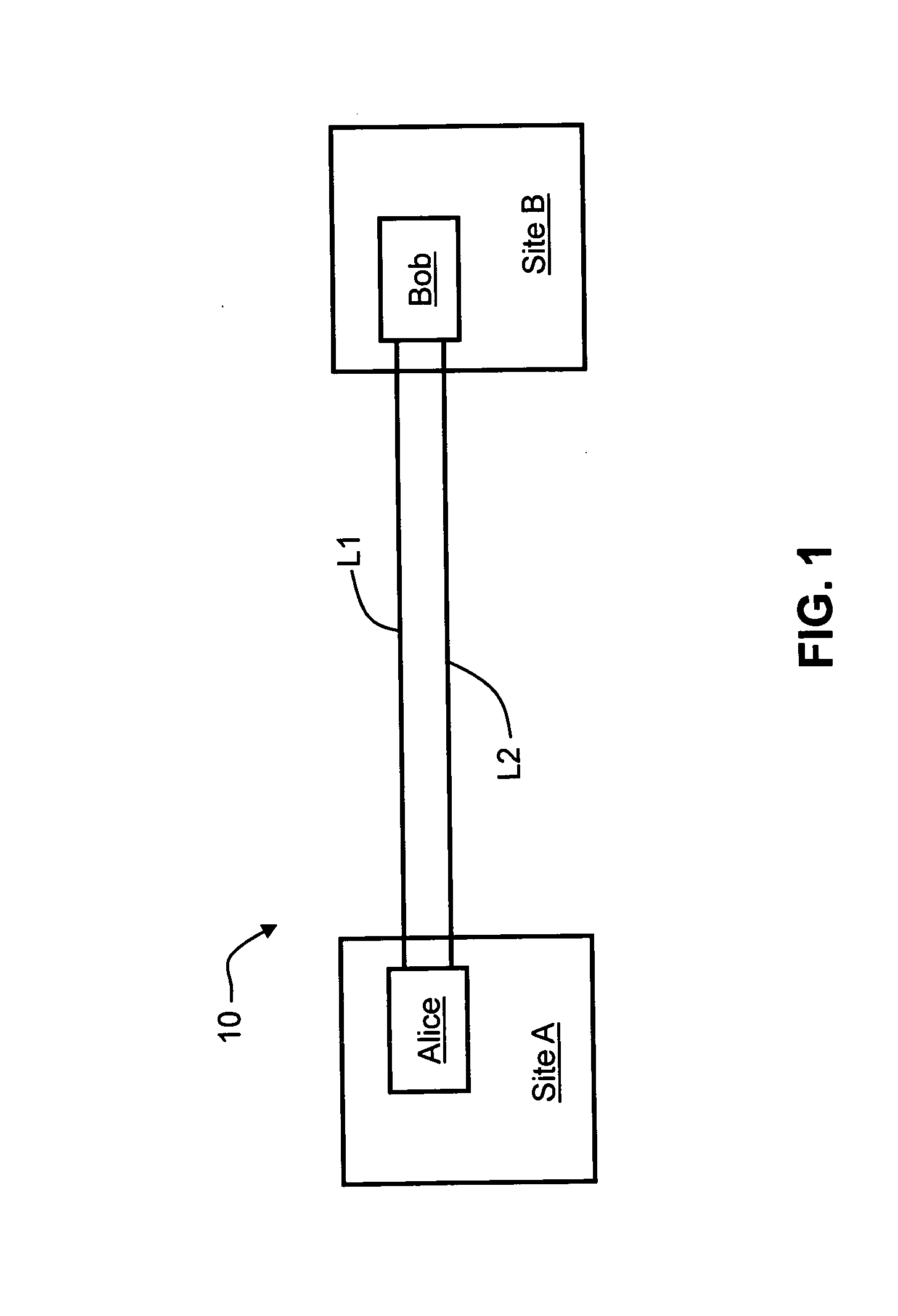
[0014]FIG. 1 is schematic diagram of a QKD system 10 having a first transmitting QKD station Alice at a first site (Site A) and a second receiving QKD station Bob at a second site (Site B), with the two QKD stations optically coupled by two communication links (“links”) L1 and L2. For the purposes of discussion herein, link L1 is considered the “primary” link and link L2 is considered the “secondary” QKD link. In an example embodiment of the present invention, one or both of links L1 and L2 are or include optical fibers. In another example embodiment, links L1 and L2 are free-space links.

Alice

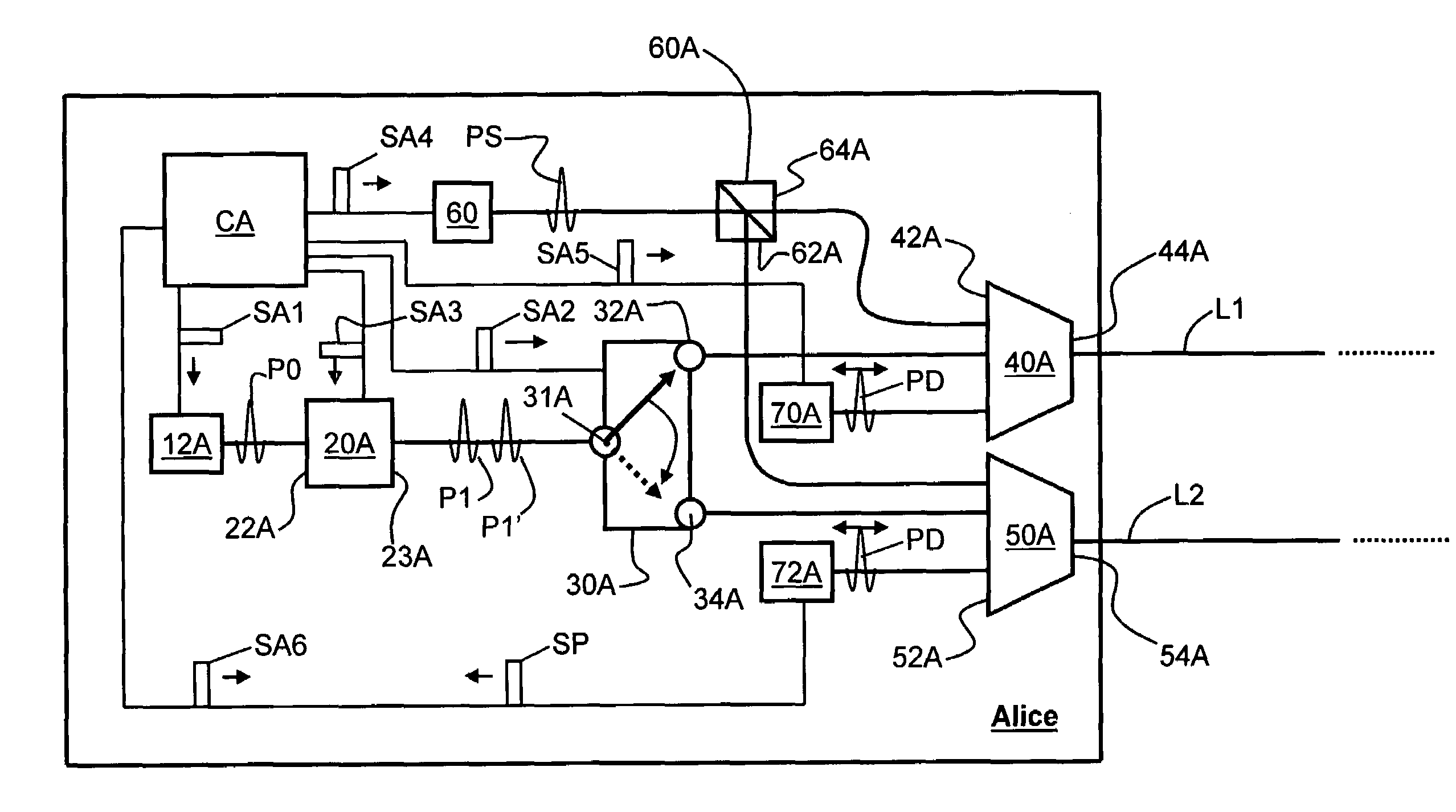
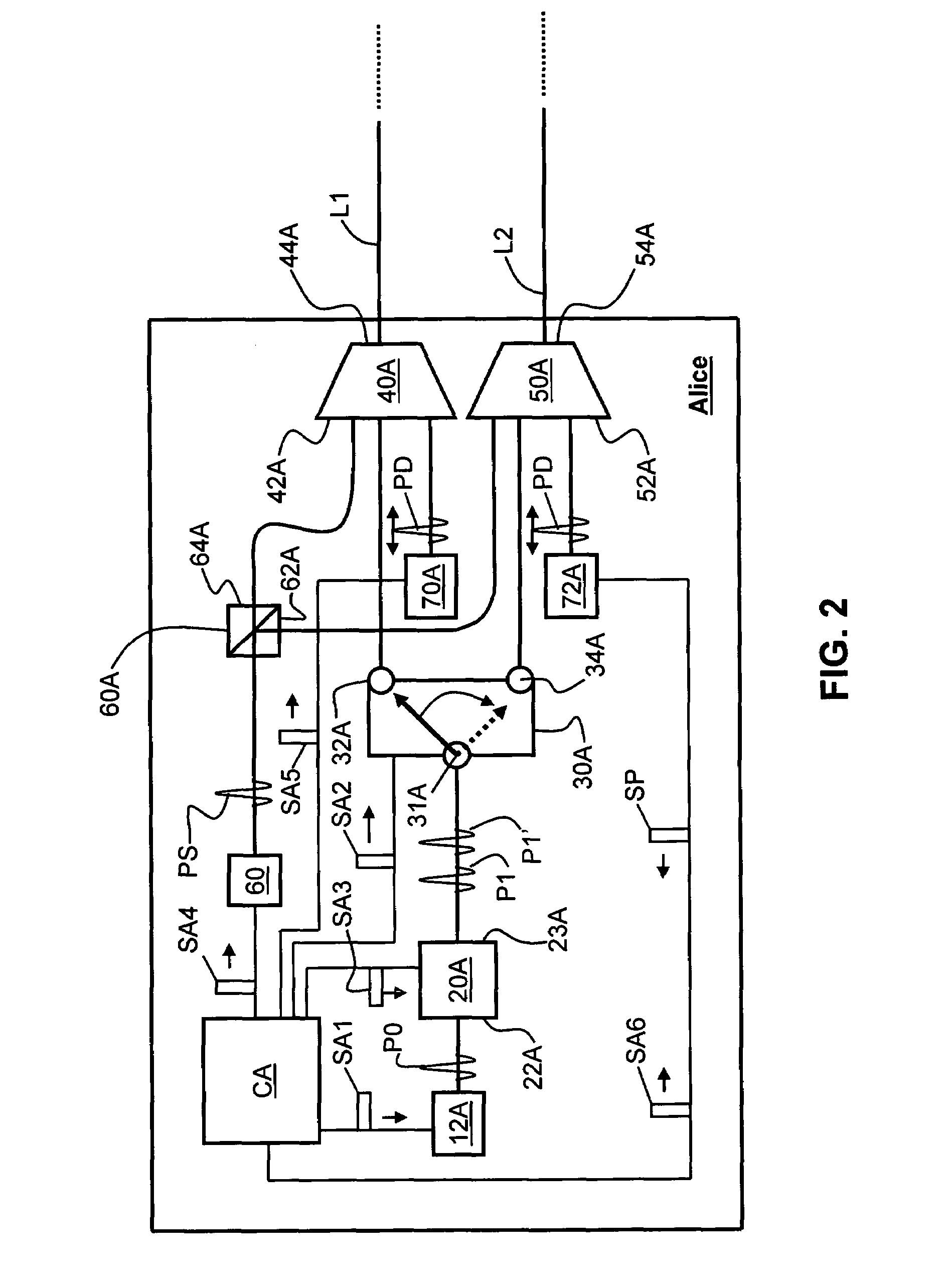
[0015]FIG. 2 is a close-up schematic diagram of an example embodiment of the QKD station Alice of QKD system 10 of FIG. 1. Alice includes a light source 12A adapted to generate either single photons or weak photon pulses P0. An encoding optical system 20A having an input end 22A and an output end 23A is optically coupled to light source 12A at input end 22A. Encoding optical system 20A is adapt...


PUM


Abstract

A QKD system having QKD link redundancy between two sites, with the system having only one QKD station at each site, and with two or more QKD links operably coupled to the QKD stations. The QKD stations have respective optical switches that are optically coupled to both QKD links and that are controlled by respective controllers in each of the QKD stations. If one of the QKD links fails or has trouble transmitting optical signals, the QKD switches are switched so that the optical path between the QKD stations uses the remaining QKD link. This arrangement requires only two QKD stations rather than the four QKD stations as presently taught in the prior art.

Description

CLAIM OF PRIORITY[0001]This application claims the benefit of priority under 35 U.S.C. § 119(e) from U.S. Provisional Patent Application Ser. No. 60 / 880,975, filed on Jan. 18, 2007.FIELD OF THE INVENTION[0002]The present invention relates generally to quantum key distribution (QKD), and in particular relates to systems and methods for providing communication link redundancy between QKD stations of a QKD system without having to add additional QKD stations.BACKGROUND ART[0003]QKD involves establishing a key between a sender (“Alice”) and a receiver (“Bob”) by using either single-photons or weak (e.g., 0.1 photon on average) optical signals (pulses) called “qubits” or “quantum signals” transmitted over a “quantum channel.” Unlike classical cryptography whose security depends on computational impracticality, the security of quantum cryptography is based on the quantum mechanical principle that any measurement of a quantum system in an unknown state will modify its state. Consequently, ...

Claims


Application Information

Patent Timeline
IPC IPC(8): H04L9/08H04K1/00H04B10/20
CPCH04B10/30H04L9/0855H04B10/70
Inventor LEE, KEUNBERZANSKIS, AUDRIUS
Owner MAGIQ TECH INC
Why Eureka
Try Eureka