Facet joint implant sizing tool

a technology for facial joints and tools, applied in the field of facial joint implant sizing tools, can solve the problems of reducing the foraminal area, radicular pain, neck pain and muscle weakness,

Inactive Publication Date: 2008-07-24
KYPHON
View PDF99 Cites 80 Cited by
  • Summary
  • Abstract
  • Description
  • Claims
  • Application Information

AI Technical Summary

Problems solved by technology

Spinal stenosis results in a reduction foraminal area (i.e., the available space for the passage of nerves and blood vessels), which compresses the cervical nerve roots and causes radicular pain.
Another symptom of spinal stenosis is myelopathy, which results in neck pain and muscle weakness.
Extension and ipsilateral rotation of the neck further reduces the foraminal area and contributes to pain, nerve root compression, and neural injury.

Method used


Image

  • Facet joint implant sizing tool
  • Facet joint implant sizing tool
  • Facet joint implant sizing tool

Examples


embodiment 1800

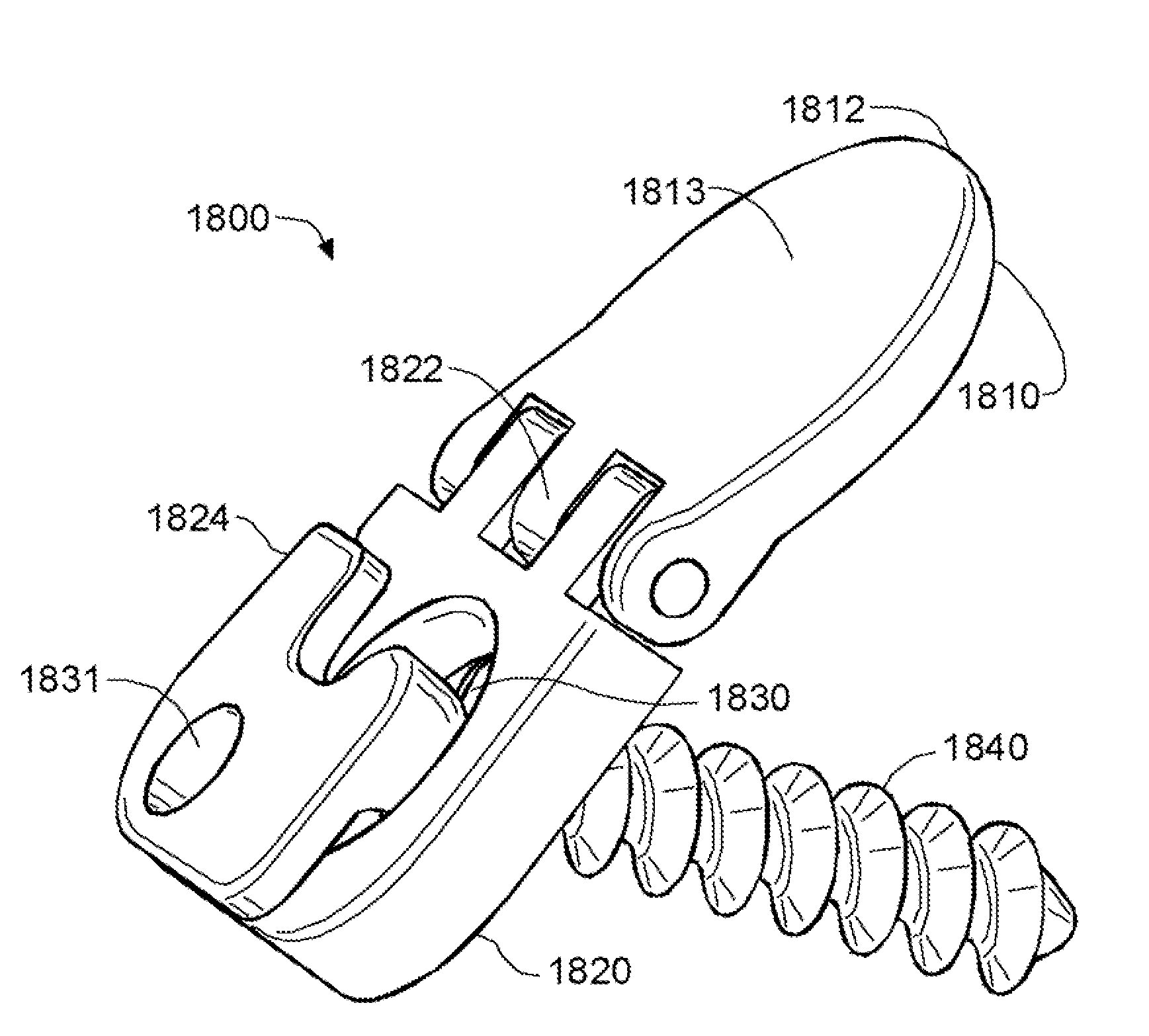
[0042]FIG. 5A and FIG. 5B depict a further embodiment 1800 of the implant. In this embodiment, an artificial facet joint spacer 1810 is connected with a lateral mass plate 1820 with a pivot 1822. The pivot 1822 allows the lateral mass plate 1820 to bend at a wide range of angles relative to the artificial facet joint and preferably at an angle of more than 90 degrees, and this flexibility facilitates positioning and insertion of the artificial facet joint spacer 1810 into a patient's facet joint, the anatomy of which can be highly variable among individuals. The pivot 1822 further facilitates customizing the anchoring of the implant, i.e., the positioning of a fixation device. The pivot enables positioning of the lateral mass plate 1820 to conform to a patient's cervical spinal anatomy, and the lateral mass plate 1820 accepts a fixation device to penetrate the bone. In an embodiment of the present invention, the spacer can be made of bone. The artificial facet joint spacer 1810 can ...

embodiment 800

[0054]In embodiments of the invention, a joint spacer 840 and a base 830 of a sizing tool closely resemble the dimension and shape of an implant which can be inserted between the facet joint, in order to best determine the appropriate dimension of implants. FIG. 8B shows an embodiment 800 of a facet joint implant sizing tool which contains cleats 872, 874, 876 (FIG. 11) on the surface 870 of the joint spacer 840 which engage the superior articular processes of one vertebrae while the surface engaging the inferior articular process of the above vertebrae, is smooth in order to facilitate sliding the joint spacer 840 into the gap between these processes. In an embodiment of the invention, the cleats 872, 874, 876 can be spaced over the length of the surface 870 of the joint spacer 840. As shown in FIG. 8C in an embodiment of the invention, the cleats 872, 874, 876 can be spaced over the breadth of the surface 870 of the joint spacer 840. This is similar in design to the artificial joi...


PUM


Abstract

In an embodiment of the present invention, a tool resembles an implant for positioning within a cervical facet joint. The tool can be used for distracting and/or sizing the cervical facet joint and thereby distracting the cervical spine and increasing the area of the canals and openings through which the spinal cord and nerves must pass, and decreasing pressure on the spinal cord and/or nerve roots. The tool can be inserted laterally or posteriorly.

Description

CROSS-REFERENCE TO RELATED APPLICATIONS[0001]This application is related to U.S. application Ser. No. 11 / 053,346, entitled INTER-CERVICAL FACET IMPLANT AND METHOD, filed Feb. 8, 2005 [Our Reference No. SFMT-0122US1]; U.S. application Ser. No. 11 / 053,399, entitled INTER-CERVICAL FACET IMPLANT AND METHOD, filed Feb. 8, 2005 [Our Reference No. SFMT-01118US1]; U.S. application Ser. No. 11 / 053,624, entitled INTER-CERVICAL FACET IMPLANT AND METHOD, filed Feb. 8, 2005 [Our Reference No. SFMT-01118US2]; U.S. application Ser. No. 11 / 053,735, entitled INTER-CERVICAL FACET IMPLANT AND METHOD, filed Feb. 8, 2005 [Our Reference No. SFMT-0118US3, which are each, expressly incorporated herein in full, by reference.TECHNICAL FIELD[0002]This invention relates to a facet joint implant sizing tool used for sizing implants prior to insertion between the spinous processes.BACKGROUND OF THE INVENTION[0003]The spinal column is a bio-mechanical structure composed primarily of ligaments, muscles, vertebrae ...

Claims


Application Information

Patent Timeline
Patent Type & Authority Applications(United States)
IPC IPC(8): A61B17/56
CPCA61B17/86A61F2/4405A61F2220/0091A61F2002/30471A61F2/4684A61B17/56
Inventor WINSLOW, CHARLES J.MITCHELL, STEVEN T.YERBY, SCOTT A.
Owner KYPHON
Why Eureka
Try Eureka