Drying apparatus and methods

Inactive Publication Date: 2008-07-31
INTERNATIONAL FLAVORS & FRAGRANCES
View PDF22 Cites 10 Cited by
  • Summary
  • Abstract
  • Description
  • Claims
  • Application Information

AI Technical Summary

Benefits of technology

[0028]FIG. 3D is a side elevation diagram showing an alternative

Problems solved by technology

While spray dryers are known to provide high processing capacity at a relatively low production cost, the resulting product quality is known to be relatively low.
On the other hand, freeze dryers are known to produce products of high quality, but at a relatively high production cost.
Several characteristics of the drying apparatus and method disclosed by the '837 patent lead to inconvenient and troublesome use of the apparatus.
As a result, the apparatus occupies a relatively large amount of production space.
Also, several potential problems regarding the operation of the prior art apparatus can be attributed to the use of water as a heat source.
The water heating and circulation system 15 can prove troublesome in several ways.
First, the water heating and circulation system 15 adds complexity to the configuration and construction of the apparatus as well as to its operation.
The required water heating and circulation system 15 can also deter the ease of mobility of the prior art dryer because of the bulky nature of the system and because of the need for a water supply.
However, because the temperature of the water heat source of the prior art apparatus never exceeds 100 degrees C., the difference in the temperatures of the heat source and the product 20 is limited which, in turn limits the transfer of heat to the product.
Also, the prior art apparatus and method of the '837 patent does not provide for any flexibility in processing temperatures because the temperature of the heat source cannot be easily changed, if at all.
However, because the temperature of the heat source of the prior art apparatus is not only limited to 100 degrees Centigrade, but also slow to change, the temperature profile of the product cannot be easily controlled, or changed.
Because the prior art apparatus disclosed by the '837 patent employs water as a heat source, and requires a large water heating system for its operation, the resulting prior art apparatus is large, heavy, immobile, complex, difficult to maintain, and can be a source of microbial contamination of the product.
Additionally, because the temperature of the water heat source utilized by the prior art method and apparatus is limited to less than 100 degrees Centigrade, the prior art method of drying can be slow and inefficient, and does not provide for modification or close control of the product temperature profile.

Method used


Image

  • Drying apparatus and methods
  • Drying apparatus and methods
  • Drying apparatus and methods

Examples


first embodiment

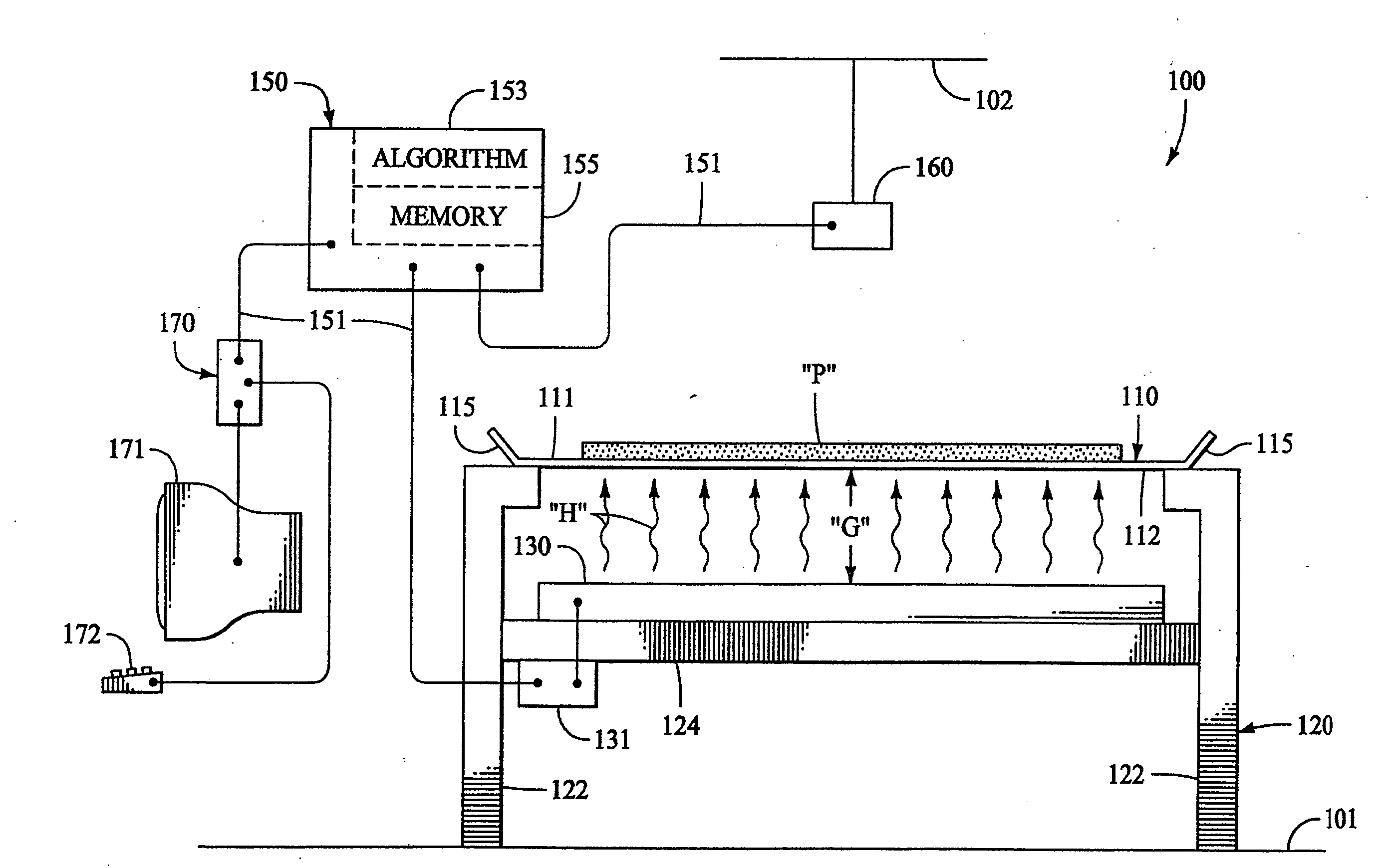
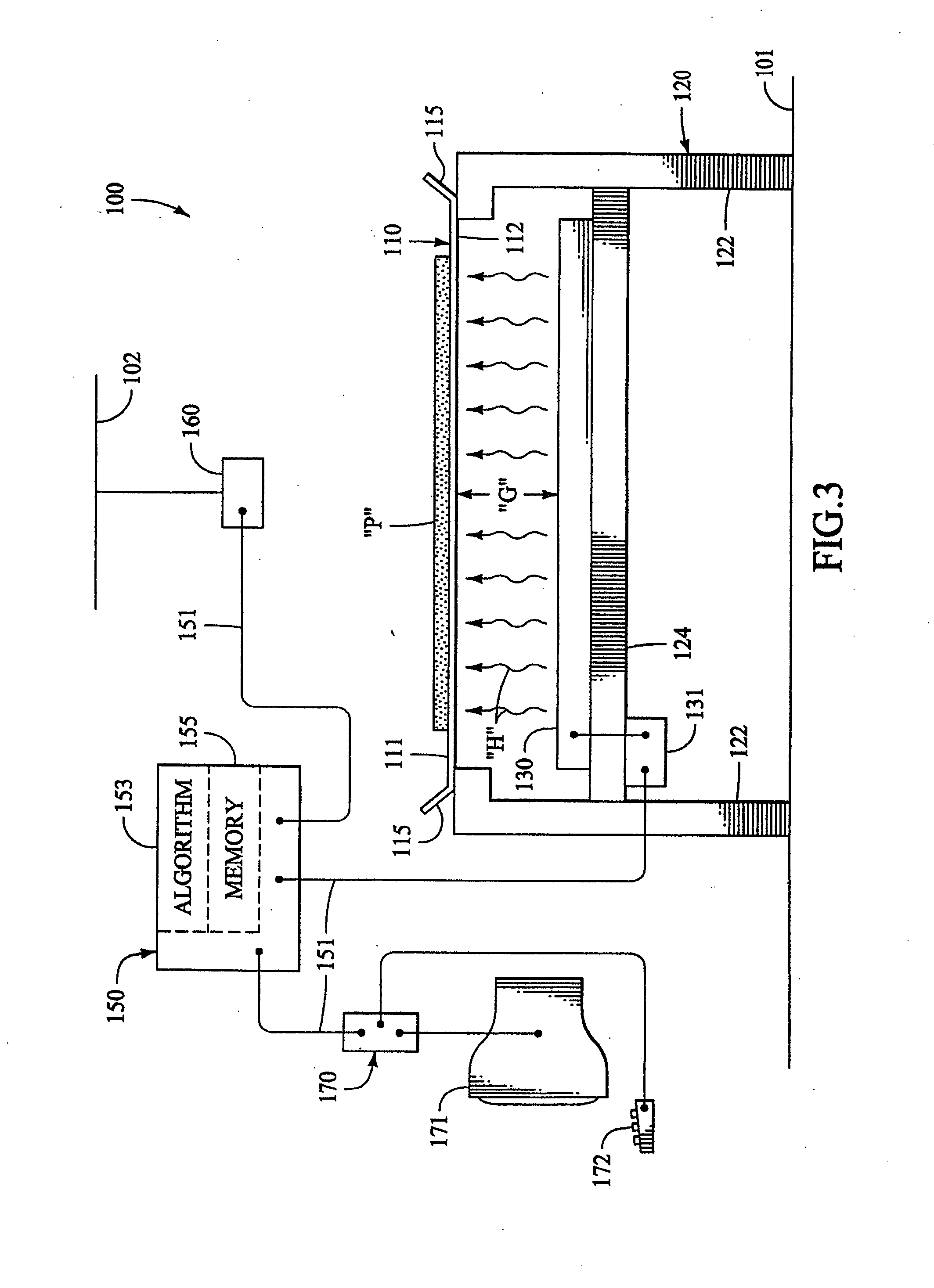
[0032]Referring to FIG. 3, a side elevation view of a basic drying apparatus 100 in accordance with the present invention is depicted. The drying apparatus 100 is generally configured to remove a given amount of moisture from a product “P” to dry or concentrate the product. The product “P” can be in any of a number of types, including aqueous colloidal suspensions, or the like, which can be in the form of a liquid or paste, and from which moisture is to be removed there from by heating. The product “P” is generally spread, or otherwise placed, onto the apparatus 100 for drying. Once the product “P” has reached the desired dryness, it is then removed from the apparatus 100.

[0033]The apparatus comprises a support surface 110 onto which the product “P” is placed for drying. The support surface 110 has a first side 111 which is configured to support a layer of the product “P” thereon as shown. The support surface also has second side 112 which is opposite the first side 111. Preferably,...

second embodiment

[0051]For example, referring to FIG. 3A, a side elevation diagram is shown of an apparatus 100A in accordance with the present invention. As is evident, the support surface 110A of the apparatus 100A is configured as an endless belt comprising a flexible sheet supported by rollers 123. The support surface 110A can be configured to move, or circulate, in the direction “D.”

[0052]The rollers 123 are, in turn, supported by the chassis 120A which also supports at least one heat source 130. The heat source 130 is configured to direct radiant heat “H” toward the second side 112 of the support surface 110A. Opposite the second side 112, is the first side 111 of the support surface 110A which is configured to movably support the product “P” thereon. As is seen, the configuration of the apparatus 100A can provide for continuous processing of the product “P.”

third embodiment

[0053]Turning now to FIG. 3B, a side elevation diagram is shown which depicts an apparatus 100B in accordance with the present invention which is similar to the apparatus 100A discussed above for FIG. 3A. However, the support surface 110B of the apparatus 100B is not only configured as an endless belt, but also comprises a plurality of rigid links 113 which are pivotally connected to one another in a chain-like manner.

[0054]As shown, the apparatus 100B comprises a chassis 120 which rotatably supports rollers 123 thereon. The rollers 123 in turn movably support the support surface 110B thereon, which can be configured to move, or circulate, in the direction “D.” The chassis 120 also supports a heat source 130 thereon which is configured to direct radiant heat “H” toward the second side 112 of the support surface 110B. The support surface 110B is configured to support the product “P” on the first side 111 which is opposite the second side 112.


PUM


Abstract

Apparatus and method for drying a product comprising placing the product on a first side of a support surface, and directing dry radiant heat toward the second side of the surface to heat the product. A sensor can be included to measure at least one characteristic of the product, such as the temperature or moisture content thereof. The temperature of the heat source can be regulated as a function of the measured characteristic. The support surface can also be made so as to be movable relative to the heat source. In an alternative embodiment, a plurality of control zones are defined and through which the product is successively passed. Each of the control zones has at least one associated heat source and an associated sensor so as to regulate the temperature of the heat sources associated with each control zone independently of those associated with another zone.

Description

CROSS REFERENCE TO RELATED APPLICATIONS[0001]The present application is a divisional application of co-pending U.S. patent application Ser. No. 10 / 367,465, filed on Feb. 14, 2004, which was a divisional application of U.S. patent application Ser. No. 09 / 757,323, filed on Jan. 9, 2001, issued as U.S. Pat. No. 6,539,645.FIELD OF THE INVENTION[0002]The present invention relates to methods and apparatus for drying a product, and more specifically, to methods and apparatus for drying a product which is in the form of a liquid or paste by removing moisture there from.BACKGROUND OF THE INVENTION[0003]Prior art drying apparatus and methods have been utilized for drying organic products which are in the form of liquids or semi-liquids such as solutions and colloidal suspensions and the like. These prior art drying apparatus have been used primarily to produce various dried or concentrated foodstuffs and food-related products, as well as nutritional supplements and pharmaceuticals. The liquid...

Claims


Application Information

Patent Timeline
IPC IPC(8): F26B19/00F26B3/28F26B3/30F26B17/02F26B17/04
CPCF26B3/28F26B17/04F26B17/023F26B3/305F26B13/10
Inventor SAVARESE, MARK
Owner INTERNATIONAL FLAVORS & FRAGRANCES
Why Eureka
Try Eureka