
Method for providing graphical user interface for changing reproducing time point and imaging apparatus therefor

a technology of reproducing time and graphical user interface, which is applied in the direction of selective content distribution, television systems, instruments, etc., can solve the problems of inconvenient user inconvenience and the inability to locate the desired time poin

Inactive Publication Date: 2008-07-31
SAMSUNG ELECTRONICS CO LTD
View PDF34 Cites 71 Cited by
  • Summary
  • Abstract
  • Description
  • Claims
  • Application Information

AI Technical Summary

Benefits of technology

[0009]Accordingly, aspects of the present invention address at least the above problems. Also, the present invention is not required to overcome the problems described above, and an exemplary embodiment of the present invention may not overcome any of the problems described above.

Problems solved by technology

Accordingly, it is impossible to locate the desired time point by changing the reproducing time point once, and a user usually locates the desired time point after numerous trials and errors.
Further, the longer the length of the moving image, the more the user is inconvenienced.

Method used


Image

  • Method for providing graphical user interface for changing reproducing time point and imaging apparatus therefor
  • Method for providing graphical user interface for changing reproducing time point and imaging apparatus therefor
  • Method for providing graphical user interface for changing reproducing time point and imaging apparatus therefor

Examples


Embodiment Construction

[0035]Certain exemplary embodiments of the present invention will be described in greater detail with reference to the accompanying drawings.

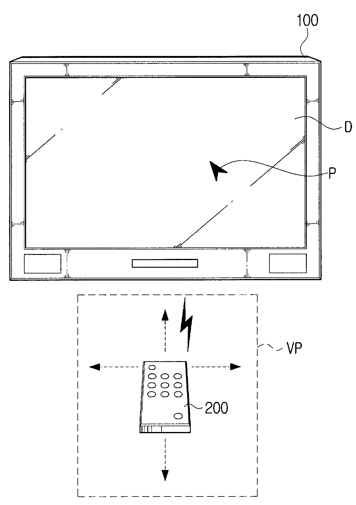
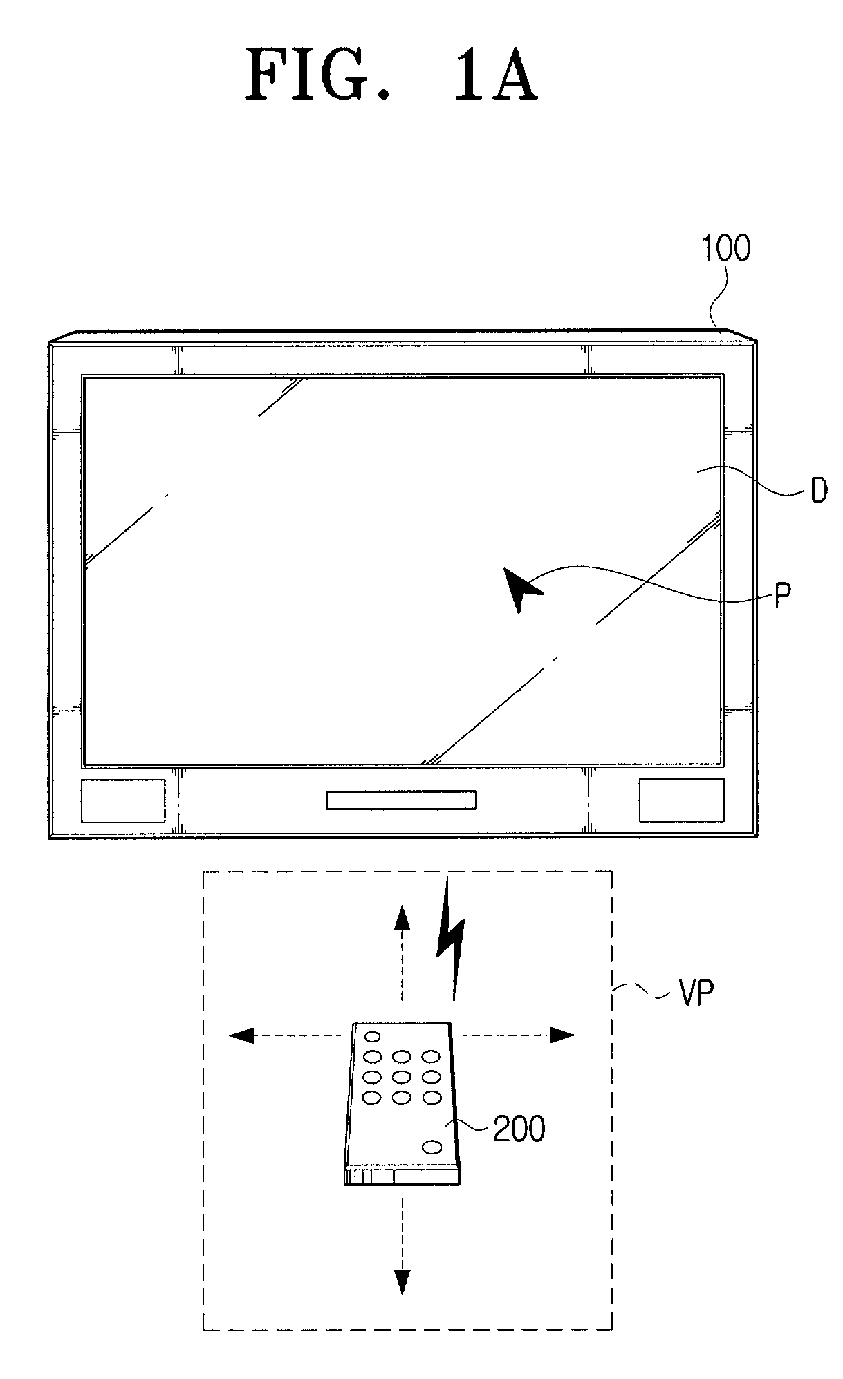
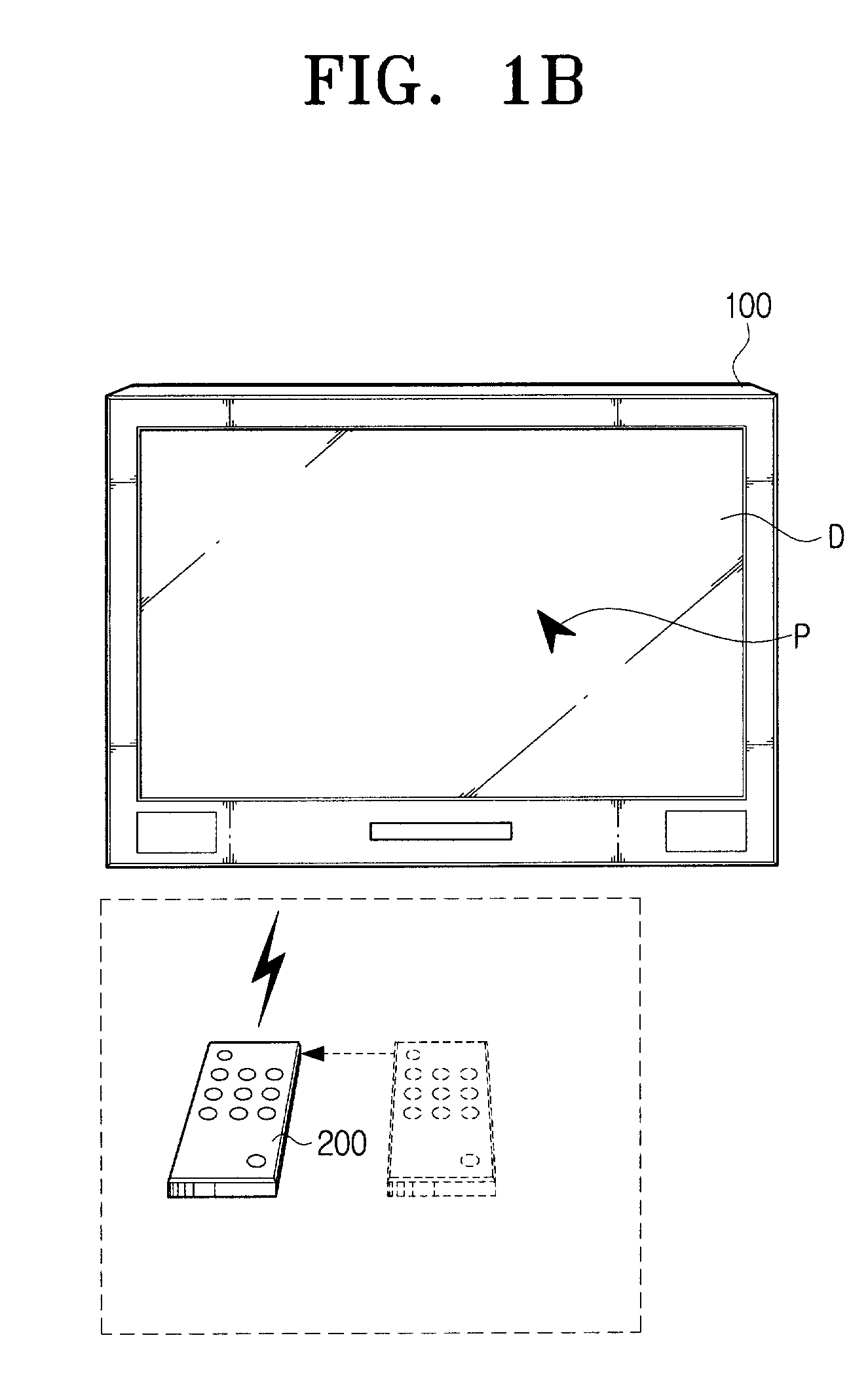
[0036]FIG. 1A is a view illustrating a broadcast receiving system according to an exemplary embodiment of the present invention. Referring to FIG. 1A, a broadcast receiving system comprises a digital television (DTV) 100 as a broadcast receiving apparatus and a remote control 200 as a user input apparatus (remote control apparatus).

[0037]The DTV 100 provides a user with a broadcast received over wire or wirelessly, through a display D. A pointer P is displayed on the display D. Additionally, the DTV 100 may provide a user with an external input received from an external apparatus which is connected over wire or wirelessly, through the display D, and may also provide a user with a broadcast by reproducing a file, such as a moving image file, a still image file, a music file, etc., stored in a built-in storage media.

[0038]The remote control 200 s...


PUM


Abstract

A method for providing a Graphical User Interface (GUI) for changing a reproducing time point, and an imaging apparatus incorporating the same are provided. The GUI for changing a reproducing time point displays reduction images of specific time points within a time period including a specific time point selected by a pointer, and changes the reproducing time point to the time point represented by the reduction image selected from the displayed reduction images. Accordingly, a user is able to search for a desired time point without going through a plurality of manipulations to change the reproducing time point on the progress bar using the pointer.

Description

CROSS-REFERENCE TO RELATED APPLICATIONS[0001]This application claims priority from Korean Patent Application No. 10-2007-0008530, filed Jan. 26, 2007, in the Korean Intellectual Property Office, the entire disclosure of which is hereby incorporated by reference.BACKGROUND[0002]1. Field of the Invention[0003]Methods and apparatuses consistent with the present invention relate to providing a Graphical User Interface (GUI) for changing a reproducing time point, and more particularly, to providing GUI for changing a current reproducing time point and an image apparatus incorporating the same.[0004]2. Description of the Related Art[0005]A progress bar is widely used to represent a current reproducing time point while a moving image is reproduced. The progress bar represents the length of whole moving image in a bar form, and represents the current reproducing time point by moving the bar.[0006]If a reproducing time point that is different from the current reproducing time point is select...

Claims


Application Information

Patent Timeline
IPC IPC(8): G06F3/033G06F3/048G06F3/0481H04N5/445
CPCG06F3/0481G06F3/04842G11B27/34H04N5/44591H04N5/76H04N5/781H04N21/4316H04N21/42222H04N21/440263H04N21/440281H04N21/47217H04N21/8153H04N21/8455G11B19/025G06F3/0482G11B27/105H04N21/47
Inventor YUN, YOUNG-HWAJON, SEONG-ICKKIM, JOON-HWANLEE, JEONG-YEONHWANG, WOO-SEOKYUN, HYUN-KYU
Owner SAMSUNG ELECTRONICS CO LTD
Learn More