Computer pointing input device

a technology of input device and computer, which is applied in computing, instruments, electric digital data processing, etc., can solve the problems of not being easily adapted to other display systems, liquid crystal displays (lcds), and devices that do not allow cursor images to follow almost instantaneously along the line of sight of the devi

Inactive Publication Date: 2008-07-31
NEW ERA IP
View PDF23 Cites 45 Cited by
  • Summary
  • Abstract
  • Description
  • Claims
  • Application Information

AI Technical Summary

Benefits of technology

[0011]The computer pointing input device allows a user to determine the position of a cursor on a computer display. The position of the input device in relation to the display controls the position of the cursor, such that when a user points directly at the display, the cursor appears at the intersection of the display and the line of sight from an aiming point of the input device. When the device is moved, the cursor appears to move on the display in exact relation to the input device. In addition, a cursor command unit allows the user to virtually operate the input device so that changes in the position of the device invoke mouse functions. The computer pointing input device is designed to operate with a computer having a processor through a computer communication device.

Problems solved by technology

However, both types of input devices require that the user be tied to the desktop, as a mouse pad is still necessary.
Although some input devices do exist that are not tied to a desktop, the devices do not allow for a cursor image to almost instantaneously follow along the line of sight of the device.
Although optical methods are known, such as “light guns” or “marker placement” systems, such systems are typically limited to use with cathode ray tube monitors only, and may not be easily adapted to other display systems, such as liquid crystal displays (LCDs).
Such systems limit the range of movement of the user's hand and require the camera or other sensor to be built into the handheld device, which may be bulky and not ergonomic.
Such systems also do not use a true line-of-sight imaging method, which reduces accuracy.
After repeated use, however, these buttons or wheels often tend to stick, causing problems for the user.
Additionally, use of the buttons and wheels may not be the most efficient or ergonomic method of invoking mouse functions.

Method used


Image

  • Computer pointing input device
  • Computer pointing input device
  • Computer pointing input device

Examples


first embodiment

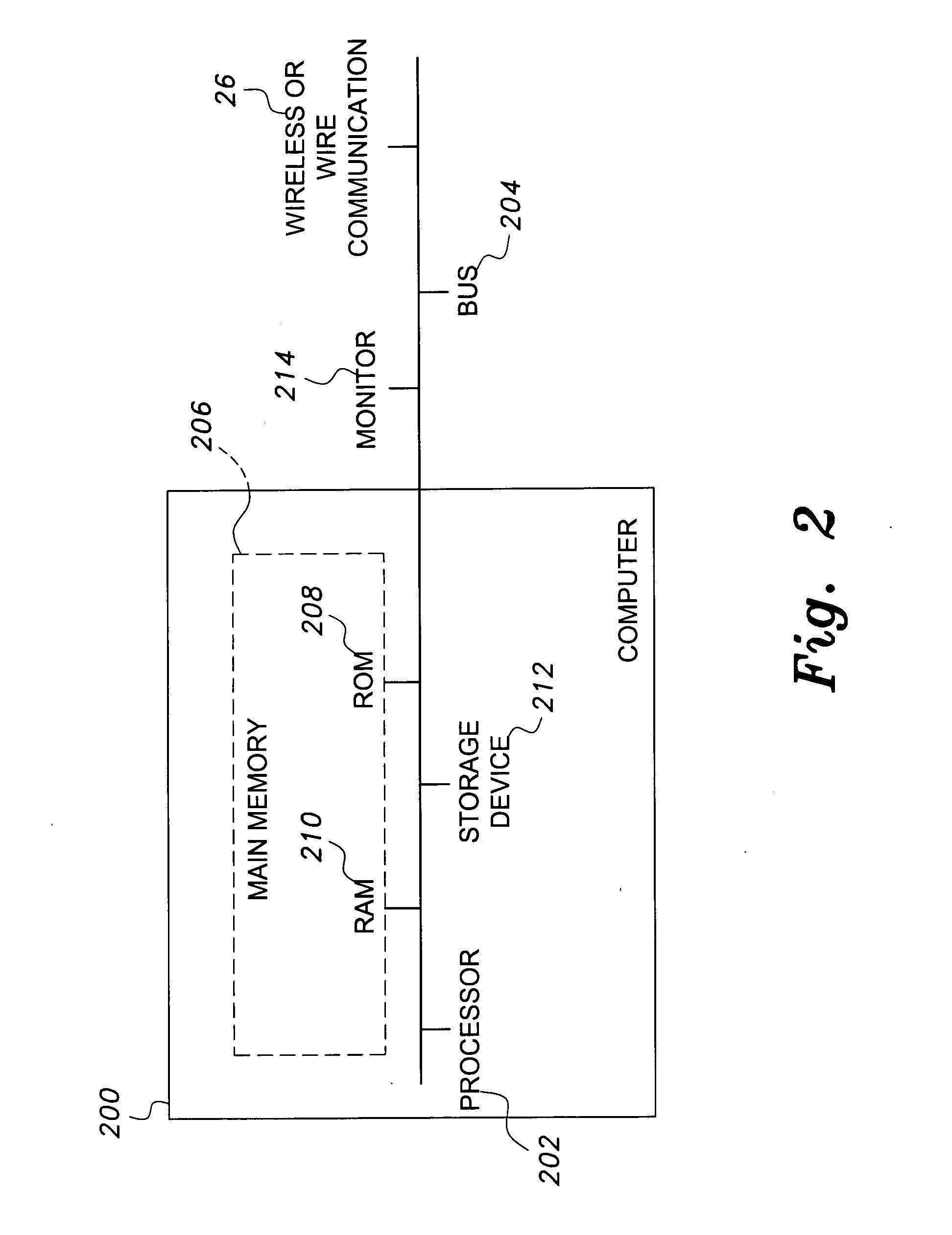
[0049]FIGS. 3 and 4 are perspective and exploded views, respectively, of the computer pointing input device 10a. The input device 10a has a housing 12 and may include an image-capturing component 16. The input device 10a additionally may include an internal processing unit 18, a battery 20, an array component 22, an array aperture 24, a wireless or wired communication device 26 (a wireless device 26a being shown in FIGS. 3 and 4) and a cursor command unit 50.

[0050]The housing 12 may be any of a number of housing devices, including a handheld mouse, a gun-shaped shooting device, a pen-shaped pointer, a device that fits over a user's finger, or any other similar structure. The housing 12 may have a front aperture 28 defined within the front end 30 of the housing 12 or a rear aperture 32 defined within the back end 34 of the housing 12. Although front 28 and rear 32 apertures are shown, an aperture capable of obtaining images through any position from the housing may be used. While bot...

second embodiment

[0055]Turning now to FIG. 5, the computer pointing input device 10b is shown. In this embodiment, a rotating ball 70 is connected to the end of the input device 10b. The ball 70 includes illuminators 38 on the ball 70 and a rear aperture 32, so that an image may be acquired through the rear aperture 32 of the device 10b. The ball 70 may be rotated to create a better position to obtain the image.

third embodiment

[0056]FIG. 6 shows the computer pointing input device 10c. The device 10c omits the transmitter 26a and substitutes a cable 26b wired directly to the processor 202. In this embodiment, the battery 20 is an unnecessary component and is therefore omitted. Additionally, a traditional mouse wheel 80 and traditional mouse buttons 82 are provided on the housing 12 so that a user is able to optionally utilize these additional features.

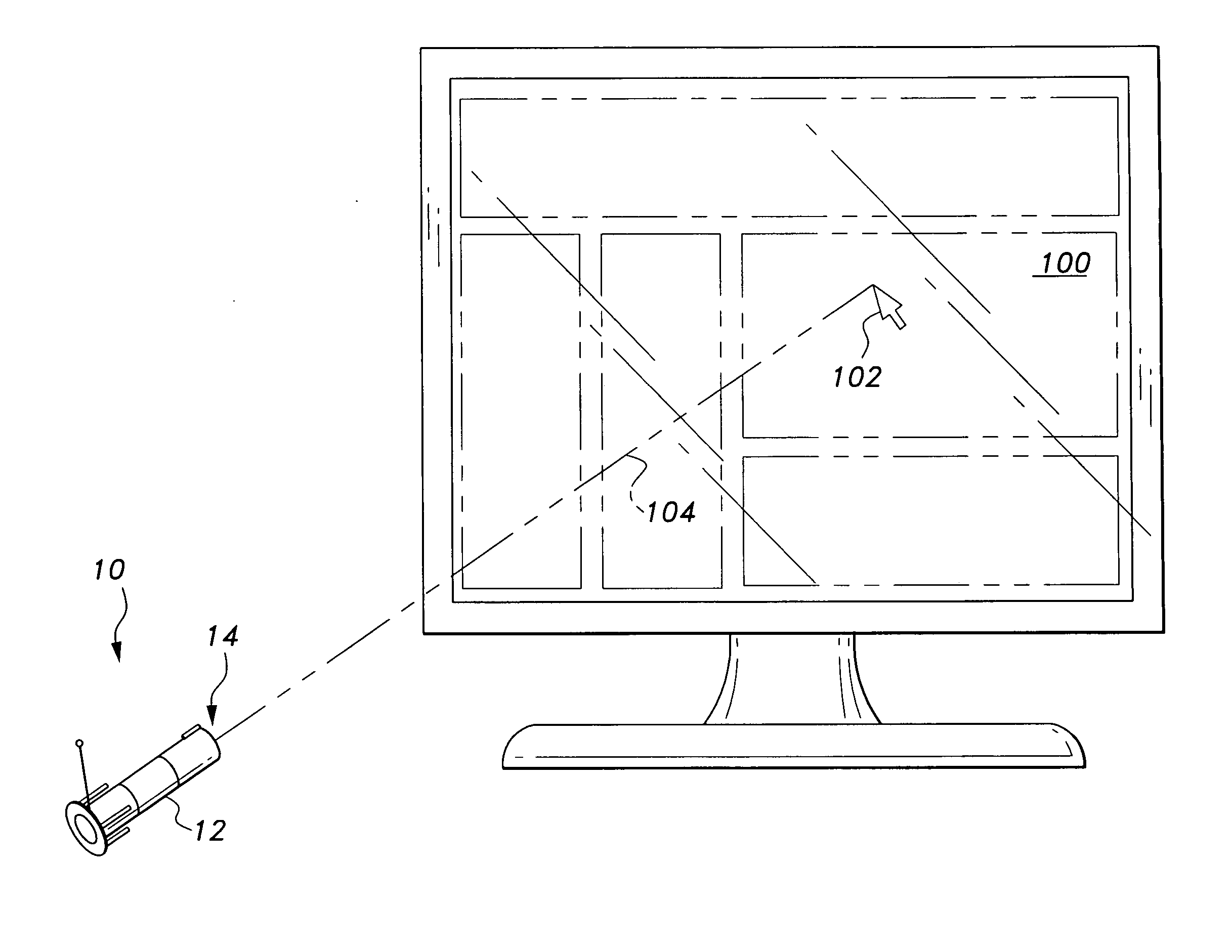
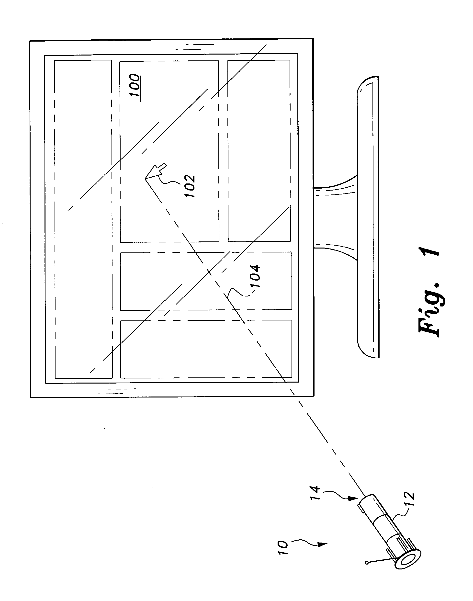
[0057]While FIGS. 3-6 show a number of embodiments, one skilled in the art will understand that various modifications or substitutions of the disclosed components can be made without departing from the teaching of the present invention. Additionally, the present invention makes use of various methods of aligning the cursor image 102 along the line of sight 104 of the computer pointing input device 10.

[0058]In a first method, the device 10 obtains a picture of the cursor image 102 and uses the picture of the cursor image 102 to align the device 10 and the curs...


PUM


Abstract

The computer pointing input device allows a user to determine the position of a cursor on a computer display. The position of the input device in relation to the display controls the position of the cursor, so that when a user points directly at the display, the cursor appears at the intersection of the display and the line of sight from of the input device. When the device is moved, the cursor appears to move on the display in exact relation to the input device. In addition, a cursor command unit allows the user to virtually operate the input device wherein changes in the position of the device allow the user to spatially invoke mouse functions. The computer pointing input device is designed to operate with a computer having a processor through a computer communication device.

Description

CROSS-REFERENCE TO RELATED APPLICATIONS[0001]This application is a continuation-in-part of U.S. patent application Ser. No. 11 / 071,467, filed Mar. 4, 2005.BACKGROUND OF THE INVENTION[0002]1. Field of the Invention[0003]The present invention relates to a computer peripheral device, and particularly to a computer pointing input device that maintains the cursor on the display with the line of sight of the input device.[0004]2. Description of the Related Art[0005]Numerous computer input devices exist that allow a user to control the movement of a cursor image on a computer display. The conventional input devices use a mechanical device connected to the housing, such as a roller ball, which, when moved about a mouse pad, determines the direction in which the cursor image is to move. Additionally, typical input devices have user-activating buttons to perform specific cursor functions, such as a “double click.”[0006]The conventional input devices have given way, in recent years, to optical...

Claims


Application Information

Patent Timeline
Patent Type & Authority Applications(United States)
IPC IPC(8): G06F3/033G06F3/038
CPCG06F3/0346G06F2203/0331G06F3/0386
Inventor GRAY, ROBERT H.
Owner NEW ERA IP
Why Eureka
Try Eureka