Eureka AIR delivers breakthrough ideas for toughest innovation challenges, trusted by R&D personnel around the world.

Method for stabilizing lens mold assembly

Inactive Publication Date: 2008-09-11
JOHNSON & JOHNSON VISION CARE INC
View PDF4 Cites 9 Cited by
  • Summary
  • Abstract
  • Description
  • Claims
  • Application Information

AI Technical Summary

Problems solved by technology

Placement of the second mold half onto the first usually results in some overflow of the lens material from the mold cavity.
However, selection of mold materials that reduce the adhesive forces can result in a back mold half that does not remain adhered to the lens material and front mold half when the mold is assembled.
However, this is disadvantageous because it increases the overall cycle time for lens manufacture and decreases output from the production line.

Method used


Image

  • Method for stabilizing lens mold assembly
  • Method for stabilizing lens mold assembly
  • Method for stabilizing lens mold assembly

Examples


Embodiment Construction

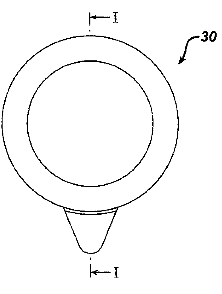
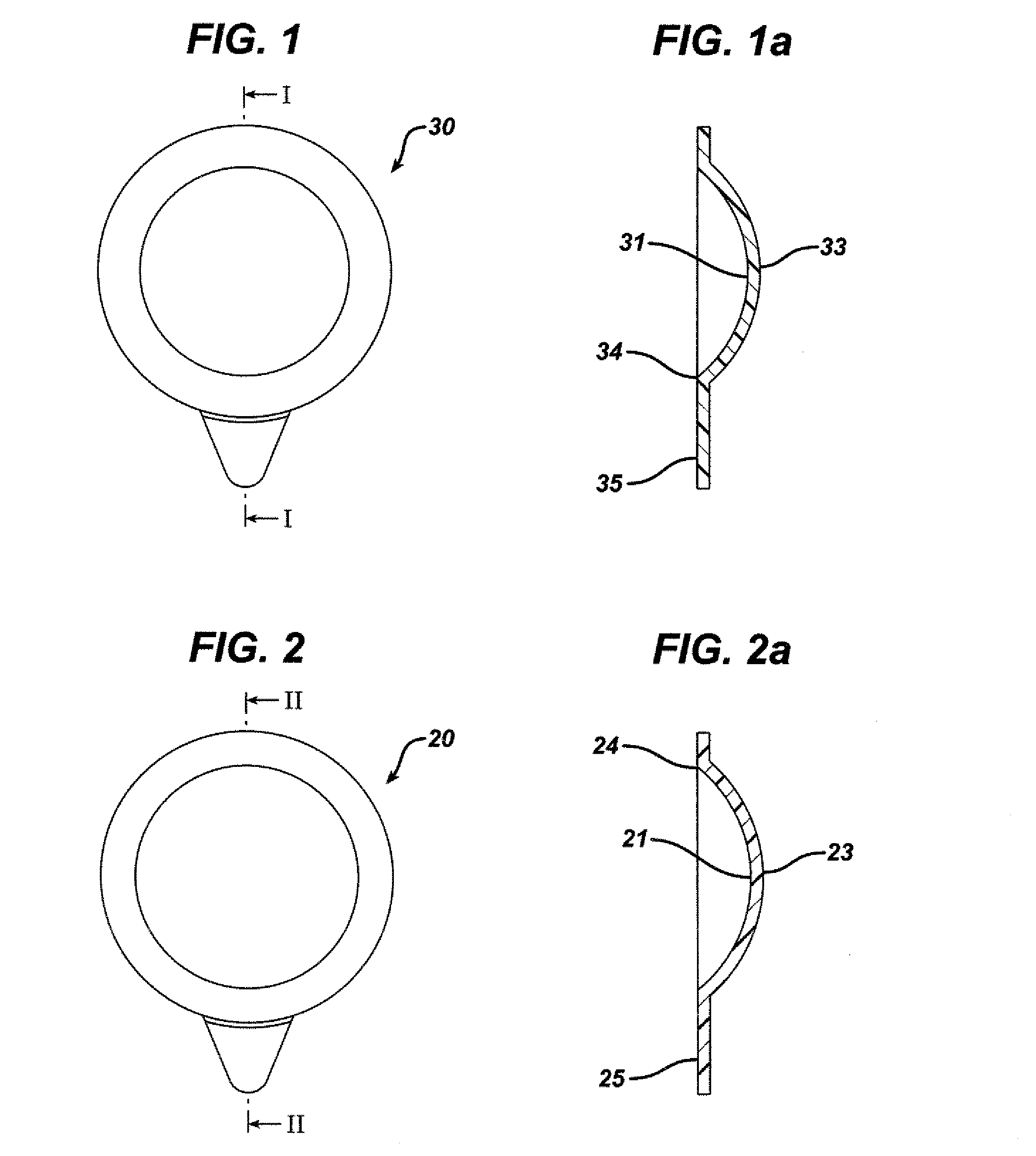
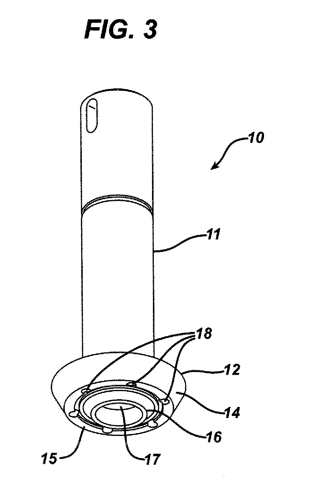
[0014]The invention provides an apparatus for, and method in which, the flash ring is partially cured at the time the back mold half is deposited onto the front mold half to form the mold assembly. It is a discovery of the invention that, by using high-intensity actinic radiation at the time of assembling the back mold half with the front mold half, the flash ring can be cured to make it sufficiently tacky so that the back mold half will remain adhered to the mold assembly during the subsequent cure process reducing center thickness variations. Thus, in the method of the invention, the pre-cure step is combined with the mold assembly step and the need for a separate pre-cure step is substantially eliminated.

[0015]In one embodiment the invention provide a method comprising, consisting essentially of and consisting of: a) depositing a predetermined amount of a lens material in a first mold half; b.) assembling the first mold half with a second mold half to form a mold and a flash ring...


PUM

PropertyMeasurementUnit
Timeaaaaaaaaaa

Abstract

The invention provides for partially curing a flash ring during mold assembly to make the ring sufficiently tacky so that the back mold half will remain adhered to the mold assembly during the subsequent cure processing.

Description

FIELD OF THE INVENTION[0001]The invention relates to the manufacture of contact lenses. In particular, the invention provide for the production of contact lenses in which the flash ring is partially cured at the time of deposition of the back mold half.BACKGROUND OF THE INVENTION[0002]Methods and molds useful in the manufacture of contact lenses are well known. For example, in U.S. Pat. No. 5,540,410, incorporated herein in its entirety by reference, are disclosed molds and their use in contact lens manufacture. Typically, two mold halves are assembled to form a mold having a mold cavity therebetween for lens formation. A reactive lens material is placed into one mold half and the second mold half is placed on the first mold half to complete the lens mold assembly.[0003]Placement of the second mold half onto the first usually results in some overflow of the lens material from the mold cavity. Typically, the mold halves have flanges extending around and outwardly from the cavity and ...

Claims


Application Information

Patent Timeline
IPC IPC(8): B29D11/00
CPCB29D11/00192B29D11/00134
Inventor KERNICK, EDWARD R.VOSS, LESLIE A.DARABI, H. ANTHONYTOKASKI, JASON M.
Owner JOHNSON & JOHNSON VISION CARE INC
Why Eureka
Eureka Blog
Learn More