Display element

Inactive Publication Date: 2008-09-11
TOSHIBA MATSUSHITA DISPLAY TECH
View PDF5 Cites 13 Cited by
  • Summary
  • Abstract
  • Description
  • Claims
  • Application Information

AI Technical Summary

Benefits of technology

[0013]By forming the same antireflective structure including a plurality of convexities with predetermined dimensions not more than the wavelength of visible light on the display surface of the display element main body and the principal surface, opposing the display surface, of the window member provided so as to o

Problems solved by technology

However, to form an antireflective coating by vapor deposition, sputtering, or the like, a thin film whose refractive index is controlled by one or a large number of times of batch processing must be formed, and this brings about problems in stability and conforming ratio of the product, and the productivity is insufficient.
To form an antireflective coating by coating, the antireflective coating must be coated on each product, and the productivity in this case is

Method used


Image

  • Display element
  • Display element
  • Display element

Examples


Embodiment Construction

[0019]Hereinafter, a constitution of a display element of an embodiment of the present invention will be described with reference to the drawings.

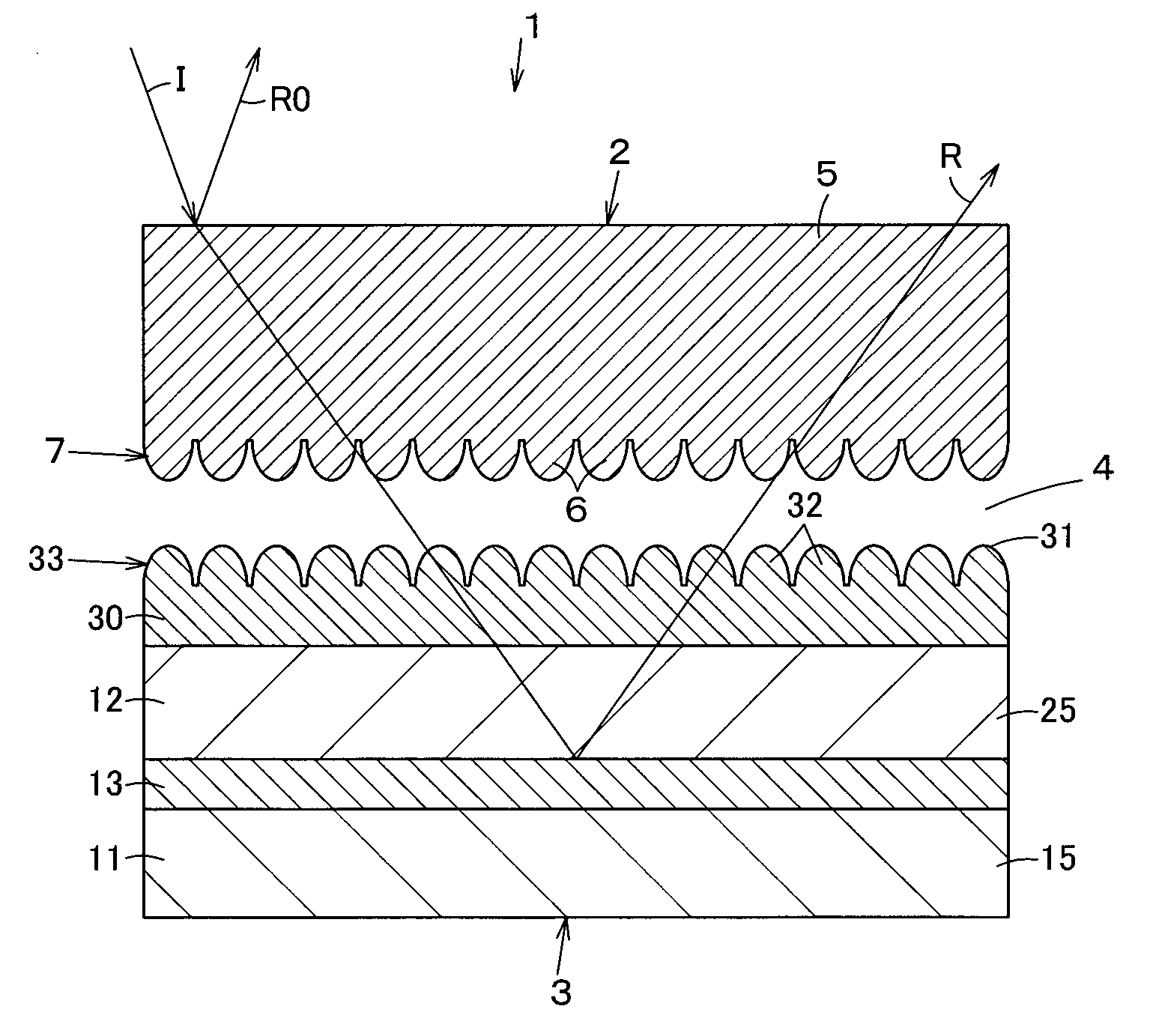
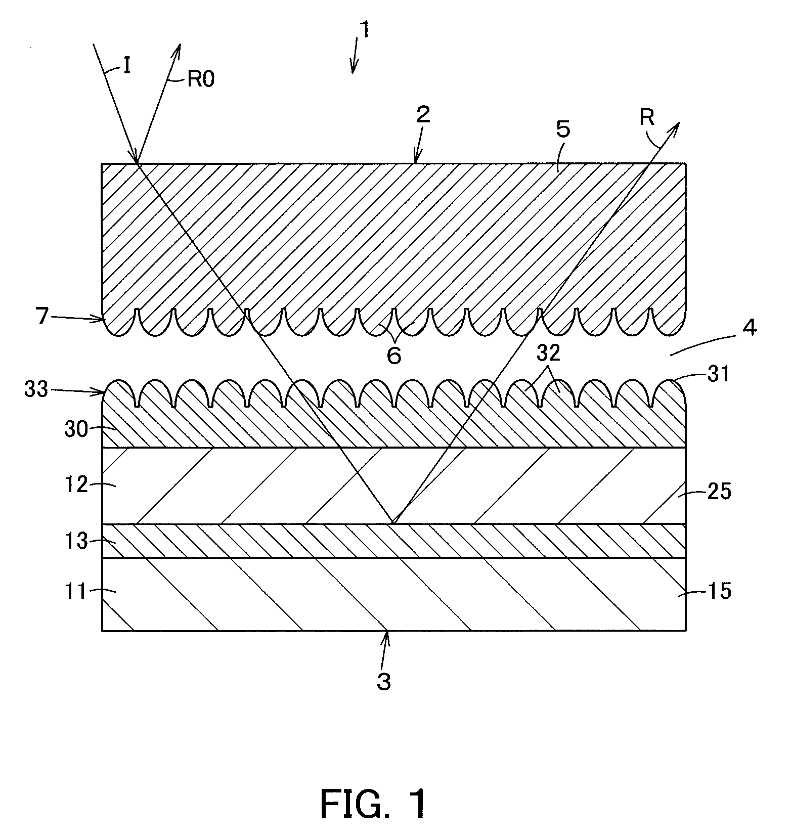
[0020]In FIG. 1, the reference numeral 1 denotes a liquid crystal display element as the display element, and this liquid crystal display element 1 is constituted so that, below a window member 2 for protection, a liquid crystal display panel 3 that is a liquid crystal display element main body as a display element main body is disposed, and between these window member 2 and the liquid crystal display panel 3, a layer of the air 4 as a medium with a refractive index of 1 is formed.

[0021]The window member 2 is positioned on the viewer side of the liquid crystal display element 1, and includes a transparent base material 5 formed into a plate shape from a predetermined transparent material, and on the back surface as a principal surface of the transparent base material 5 opposing the liquid crystal display panel 3, an antireflective structur...


PUM


Abstract

On the back surface of a window member and a display surface of a liquid crystal display panel, the same antireflective structures having a plurality of convexities with predetermined dimensions not more than the wavelength of visible light are formed, respectively. While the liquid crystal display panel is protected by the window member, reflection of external light on the back surface of the window member and the display surface of the liquid crystal display panel and reflection of outgoing light from the liquid crystal display panel can be reduced by the convexities of the antireflective structures, so that visibility can be secured.

Description

INCORPORATION BY REFERENCE[0001]The present application claims priority under 35 U.S.C. §119 to Japanese Patent Application No. 2007-055276 filed on Mar. 6, 2007. The content of the application is incorporated herein by its entirety.FIELD OF THE INVENTION[0002]The present invention relates to a display element including a window member provided so as to oppose a display surface of a display element main body.BACKGROUND OF THE INVENTION[0003]At present, various electronic equipment including mobile phones using display elements such as liquid crystal displays (LCDs) as display panels that are display element main bodies are structured so that, to protect the display element from water, dust, or external forces, the display panel is not directly exposed but a window member such as a transparent plastic plate is provided on the outside and a gap is formed between the window member and the display panel.[0004]For example, in the case of a mobile phone, a display element of a casing is c...

Claims


Application Information

Patent Timeline
IPC IPC(8): G02B27/00
CPCB82Y20/00G02B1/118G02F2202/36G02F2201/38G02F1/133504
Inventor KAWATA, YASUSHIOBI, MASAKIMURAYAMA, AKIO
Owner TOSHIBA MATSUSHITA DISPLAY TECH
Why Eureka
Try Eureka